

Could a camshaft position sensor fault on an Audi be a timing problem, an oil-soaked connector, or a damaged harness instead of a failed sensor? That question matters on EA837 and EA825 applications, where the same hard starting, stalling, or correlation fault can come from very different parts of the engine-management system.
Replacing the sensor first is tempting because it's accessible, familiar, and often associated with a clear diagnostic trouble code. It also fails regularly as a diagnostic strategy. A proper Audi camshaft sensor diagnosis separates the sensor's electrical signal from the variable valve timing actuator, the wiring that carries the signal, and the mechanical timing system that creates the reference pattern.
Table of Contents
- Camshaft Position Sensors Defined for the Enthusiast
- The EA837 and EA825 Sensor Architecture
- Locating Every Camshaft Sensor Position
- OEM Part Numbers and Platform Longevity
- Electrical Diagnostics and Wiring Schematics
- Common Failure Symptoms and Root Causes
- Diagnostic Strategy Beyond the Generic Code Reader
- Replacement Notes and Fitment Verification
Camshaft Position Sensors Defined for the Enthusiast
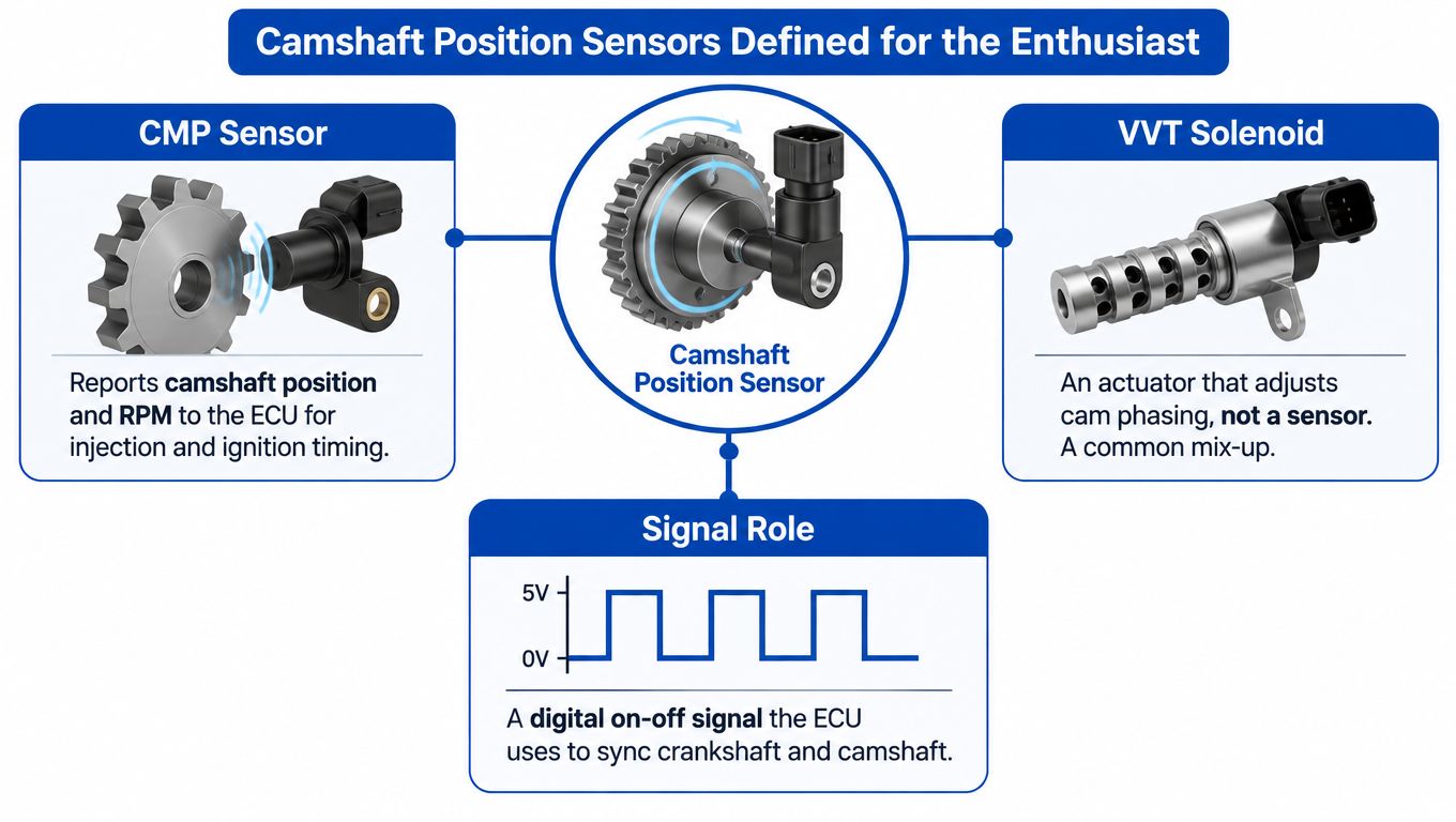
The aftermarket uses “cam sensor,” “camshaft sensor,” “cam position sensor,” and sometimes “VVT sensor” with little consistency. That terminology creates expensive confusion because a camshaft position sensor and a VVT solenoid perform different jobs.
The sensor reads the camshaft's position. The solenoid controls oil flow to a cam phaser, which changes the camshaft's angular relationship to the crankshaft. One component measures position, while the other acts on the mechanism. Replacing a solenoid because a scan tool reports a camshaft-related fault is like replacing a fuel injector because the ECU reports a crankshaft speed problem.
The sensor reads a physical reference
A camshaft sensor sits close to a toothed target, reluctor, or shaped trigger feature attached to the camshaft or its drive system. As that target passes the sensor, the internal electronics translate the changing magnetic field into a digital signal. On many VAG applications, the signal is a square wave, which the engine control unit uses to determine camshaft position for injection and ignition timing control. The electrical characteristics are documented in this Hall-effect sensor reference from AUTODOC.
The ECU compares that cam signal with crankshaft position. It uses the relationship to establish synchronization, manage starting, recognize misfire conditions, and monitor whether commanded cam phasing occurred as commanded. A missing or implausible signal can therefore create a no-start condition, not merely a warning light.
The actuator changes the target
A VVT solenoid doesn't report cam position. It meters engine oil to a hydraulic adjuster, and the adjuster changes cam timing in response to ECU commands. If the solenoid sticks, the cam may remain in the wrong position even though the sensor is reporting accurately. If the reluctor or chain timing is displaced, the sensor can also produce a valid-looking signal that doesn't match the crankshaft reference.
Practical rule: Treat the sensor, its wiring, the reluctor, the VVT actuator, and the timing drive as separate diagnostic suspects.
This distinction is especially important on performance Audi engines. The ECU doesn't just ask whether a sensor produces a pulse. It evaluates whether the pulse arrives at the expected time and whether the camshaft responds to the commanded phase angle. A replacement sensor can't correct a stretched timing system, a contaminated connector, or a sticking phaser.
The EA837 and EA825 Sensor Architecture
The correct starting point isn't the part number. It's the engine identification and the fault's physical location. Audi uses multiple camshaft signals across V6 and V8 applications, and the same engine family can appear in vehicles with different packaging, harness routing, and sensor revisions.
The EA837 3.0T and EA825 applications should therefore be treated as related but not interchangeable diagnostic environments. A scan-tool label such as “Bank 1 intake” tells you the signal designation, not automatically the easiest access route or the correct replacement part. The vehicle's VIN, engine code, model year, and installed sensor connector should all be checked before ordering.
Read the engine as a system
Each cylinder bank has its own camshaft timing events, and many applications monitor more than one camshaft position. The ECU uses those signals alongside crankshaft speed and VVT feedback. That means a single fault can be reported as a sensor circuit issue, an implausible signal, or a camshaft-to-crankshaft correlation problem depending on when the error occurs.
The practical implication is simple. Don't assume that “camshaft sensor” identifies one universal component. Confirm:
- Bank designation: Bank 1 and Bank 2 refer to different sides of the engine, and the physical orientation must be verified from Audi service information.
- Cam function: Intake and exhaust designations are not interchangeable. The connector may look similar even when the calibration and harness destination differ.
- Engine code: Model badges alone don't establish the engine configuration or sensor application.
- Fault context: A circuit fault points toward electricity, while a correlation fault can require mechanical inspection.
A useful overview of the supercharged V6 layout and related service considerations is available in this Audi V6 supercharged technical guide, but it shouldn't replace VIN-specific workshop information.
Don't infer architecture from a generic scan label
A scan tool can identify the ECU's interpretation of a signal, but it can't tell you whether oil has migrated through a connector, whether a target wheel is damaged, or whether a tensioner has allowed phase drift. Those conclusions require inspection and, where appropriate, waveform or live-data testing.
On an EA837 or EA825 vehicle, map the sensor designation to the physical bank before testing. Photograph the connector and harness routing before disassembly. If the repair involves a sensor near a cover or timing assembly, check for oil leaks and signs of harness contact at the same time. A new sensor installed into a contaminated connector only creates a fresh part with the same fault.
Locating Every Camshaft Sensor Position
Sensor locations vary with engine code and vehicle packaging, so a responsible location guide must distinguish between electrical designation and physical access. The service information for the exact vehicle should take priority over a generic internet diagram. A scan tool may identify the bank and cam function, but the technician still has to confirm which component carries that signal.
EA837 location strategy
On EA837 applications, begin by identifying the bank orientation from the vehicle's repair information. Then trace the camshaft sensor connectors toward the cylinder-head and timing-cover areas. Intake and exhaust camshaft sensors are associated with their respective camshaft positions, while additional timing-related sensors or connectors may be positioned close to the chain drive and tensioner assemblies.
Don't use “front” and “rear” as a substitute for bank and camshaft designation. Engine installation changes the visual meaning of those terms, especially when the engine is mounted longitudinally and the technician is working from the front of the vehicle. Mark each connector before removal and compare the connector keying, wire colors, and harness branch with the wiring diagram.
A practical mapping process looks like this:
- Record the fault designation from the scan tool, including bank and intake or exhaust identification where available.
- Confirm bank orientation using Audi service documentation rather than standing in front of the vehicle and guessing.
- Trace the harness branch from the ECU or main loom to the cylinder-head or timing-cover area.
- Inspect the surrounding assembly for oil seepage, damaged clips, chafing, and contact with hot components.
- Verify the replacement visually before removing the original sensor.
The access point may be under intake plumbing, near a cylinder-head cover, or close to a timing assembly depending on the vehicle and engine variant. A parts catalog is useful for confirming application, but it shouldn't be used as a substitute for locating the actual faulted circuit.
EA825 location strategy
The EA825 requires the same discipline. Identify the engine code first, then map each reported camshaft signal to its bank and cam function. The relevant sensors are installed around the cylinder-head and timing-drive assemblies, but the exact access route, connector arrangement, and component revision depend on the application.
Avoid ordering a complete set of sensors just because several cam-related codes appear together. Multiple codes can be caused by one shared power or ground fault, a harness branch problem, a connector contaminated with oil, or a mechanical timing error affecting several signals. Testing the common circuit and checking live data can distinguish a shared cause from multiple failed sensors.
If removal involves intake or exhaust hardware, document hose routing, fastener locations, and connector locks. A sensor that fits physically can still be electrically or electronically wrong for the ECU. The same caution applies to unrelated engine work. For example, installation procedures involving exhaust-side access are covered separately in this Audi header installation guide, but that information doesn't establish sensor fitment.
Workshop habit: Build the location map from the fault code, wiring diagram, and physical connector. Never build it from the sensor's appearance alone.
OEM Part Numbers and Platform Longevity
Audi part catalogs demonstrate why a search for “Audi camshaft sensor” returns a confusing mixture of applications. Catalogs show the sensor family across multiple model years and engine platforms, but a shared description doesn't mean every revision is interchangeable.
Audi OEM catalogs document Q5 applications from 2009 to 2017 using part number 07L905163C, and newer Q5 applications from 2018 to 2024 using 04C907601K. That represents at least 15 years of documented Audi platform coverage, not one universal replacement part. The application history is shown in the Advance Auto Parts Audi camshaft sensor catalog.
| Part Number | Common Application | Notes |
|---|---|---|
| 07L905163C | Audi Q5 applications from 2009 to 2017 | Earlier cataloged Q5 fitment. Confirm engine and connector before ordering. |
| 04C907601K | Audi Q5 applications from 2018 to 2024 | Newer cataloged Q5 fitment. Treat it as an application-specific revision. |
The same catalog source lists 22 different camshaft position sensor types for Audi, which reinforces the need for VIN and engine-code verification. The number describes cataloged types, not a promise that all are suitable for a particular EA837 or EA825 vehicle.
Why supersession causes mistakes
A superseded number may reflect a design revision, supplier change, connector update, or application change. Sometimes a replacement number is valid for the original application. Sometimes it belongs to a different engine family that happens to use a similar housing. The catalog's compatibility notes and the sensor's physical details must agree.
Before buying, compare the old and proposed parts for:
- Connector keying and terminal arrangement.
- Sensor body length and mounting style.
- O-ring location and sealing surface.
- Manufacturer markings and stated application.
- VIN, engine code, and ECU compatibility.
Independent listings also show broad Audi coverage. AutoZone publishes model-year coverage for the Audi A5 from 2010 through 2014 on a dedicated page, while broader compatibility listings cover Audi applications from the early 2000s through 2026, including A3, A4, A5, Q5, A6, S4, and S5 variants. Those ranges come from the Audi A5 catalog listing and AUTODOC compatibility information. They show platform breadth, not automatic fitment for your car.
Electrical Diagnostics and Wiring Schematics
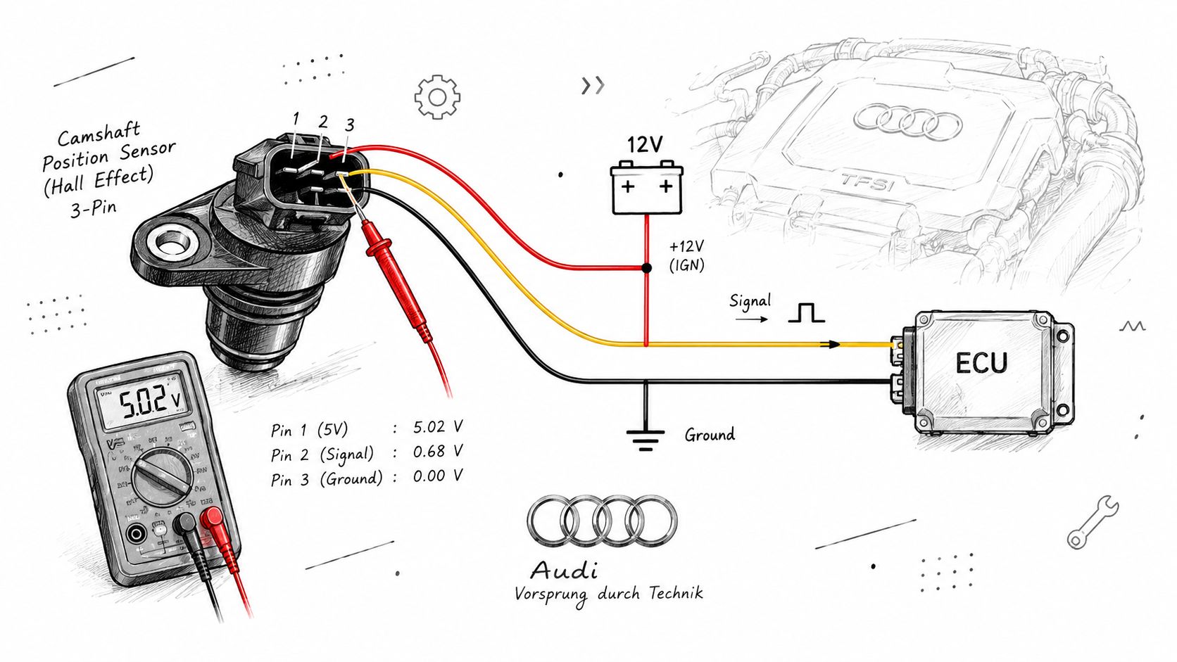
Is the Audi camshaft sensor actually defective, or is the wiring misleading you? On many VAG applications, the sensor is a three-pin Hall-effect active sensor with a power supply, ground, and signal circuit. The ECU expects a switching digital signal, but a correct component description does not prove that the sensor, connector, harness, and mechanical target are all working. HELLA's Hall-effect sensor information provides background on the sensor's operating principle.
Test the circuit before the component
Start with the wiring diagram for the exact vehicle, engine code, and ECU. Do not assume pin order from another Audi or from a replacement sensor. Back-probe the connected plug carefully, avoid spreading the terminals, and follow the service procedure for checking voltage with the circuit under its required operating conditions.
Use this sequence:
- Inspect the connector: Look for oil film, green corrosion, pushed-back terminals, damaged seals, and broken locking features. Oil in an EA837 or EA825 connector can create a false sensor-failure diagnosis.
- Check supply voltage: Confirm the expected supply with the ignition on and under the conditions specified by the service information. A reading at the disconnected plug may not prove the circuit works under load.
- Verify ground integrity: A ground can look acceptable with no load and fail while the sensor operates. Perform a voltage-drop test rather than relying only on resistance.
- Check continuity: Test each wire between the sensor connector and its control-unit destination. Move the harness gently while testing, especially near hot components and points where it is clipped or bent.
- Check for unwanted shorts: Test the signal wire for shorts to power, ground, or adjacent circuits. A short can produce implausible cam faults even when the sensor itself is sound.
- Trace oil migration: Inspect the harness beyond the plug. Oil contamination may travel inside the wiring and require harness repair, not just sensor replacement.
A multimeter can confirm supply, ground, continuity, and basic circuit behavior. It cannot show the complete camshaft-to-crankshaft timing relationship. Use an oscilloscope during cranking or idling when the circuit passes the basic checks but the fault remains.
What the waveform tells you
A functioning Hall circuit should produce clean switching as the target passes the sensor. Frequency changes with engine speed, while phase depends on camshaft position. Check whether the signal switches consistently, reaches a stable amplitude, and remains present when the complaint occurs.
Capture the waveform cold and during the fault, including after heat soak where practical. Compare the affected channel with a known-good cam signal only when the wiring diagram and test equipment support that comparison. No waveform directs attention to supply, ground, sensor, wiring, or target damage. A stable waveform at the wrong phase points toward mechanical timing or cam phasing, a common trap on these engines.
For general electrical-test technique, see this Audi MAF sensor testing reference. Use it as supporting context, not as a camshaft-specific pinout or waveform specification.
The following embedded resource can supplement the hands-on procedure:
Common Failure Symptoms and Root Causes
Could a rough idle or extended crank really prove the camshaft sensor has failed? On Audi EA837 and EA825 engines, the same complaint can result from a missing sensor signal, oil contamination at the connector, a harness fault, or mechanical timing outside the ECU's expected window.
Hot-soak symptoms deserve close attention. Hard starting, extended cranking, or stalling after reaching operating temperature can indicate a heat-sensitive electrical fault, but they can also expose marginal timing control. Begin with live data and connector inspection rather than assuming the sensor itself is defective, as advised in ClickMechanic's Audi repair guidance.
Separate electrical failure from mechanical drift
Treat the symptom as a test direction, not a diagnosis.
- Cranks without starting: Confirm whether the ECU detects cam and crank synchronization, then check sensor supply, ground, and signal during cranking.
- Intermittent stall: Inspect harness movement points, connector retention, and heat-related changes. Reproduce the fault hot if it appears only after warm-up.
- Rough idle or misfire: Check cam correlation, ignition, fueling, and mechanical timing. A camshaft code can be secondary to timing drift. For broader warning-light context, see this check engine light causes guide.
- Cold-start rattle with correlation faults: Inspect the timing system before condemning a sensor. Chain slack, tensioner wear, and cam phaser faults can create the same code pattern.
- Oil around the connector: Clean and inspect the terminals, then trace the contamination into the harness. Correct the leak before fitting a sensor, or the repair may fail again.
The key distinction is signal validity versus signal plausibility. A sensor can produce a clean square wave while the ECU rejects it because the cam event occurs at the wrong crankshaft position. That result shifts the investigation toward chain timing, tensioner behavior, reluctor alignment, or variable valve timing control.
Don't let the code choose the parts
A code reader cannot reveal oil inside a terminal or measure chain slack. It identifies where the ECU detected an abnormal condition. Use that information to select the next test, not to bypass inspection.
Diagnostic principle: When several camshaft faults appear together, inspect shared power, ground, connectors, and mechanical timing before replacing multiple sensors.
Diagnostic Strategy Beyond the Generic Code Reader
Read stored and pending DTCs before disconnecting anything. Camshaft position sensor-related faults commonly occupy the P0340 to P0344 range, but the code family only establishes a starting point. HELLA's camshaft position sensor troubleshooting guidance places code reading alongside wiring continuity and connector inspection before replacement.
Follow an evidence hierarchy
Begin with the complete fault record. Note freeze-frame data, engine temperature, cranking speed, battery condition, and whether the code returns immediately or only after a drive cycle. A generic reader may show the headline code, while a manufacturer-capable tool can provide live cam angles, synchronization status, and actuator information.
Then work through the fault in this order:
- Confirm the complaint: Reproduce the no-start, stall, rough idle, or hot-crank condition safely.
- Check related codes: A cam circuit code, a correlation code, and a low-voltage code demand different priorities.
- Inspect the connector and harness: Look for oil, corrosion, broken insulation, loose terminals, and chafing.
- Verify power and ground: Test under the relevant operating condition, not only with the connector disconnected.
- Measure continuity and shorts: Include harness movement where an intermittent fault is suspected.
- Observe live data: Compare commanded and actual cam position where the scan tool supports it.
- Capture the signal: Use an oscilloscope when the electrical diagnosis remains uncertain.
- Inspect mechanical timing: Escalate here when correlation faults, start-up rattle, or implausible phase values remain.
P0340 is not the same decision as correlation failure
A P0340-series code can direct attention to the camshaft sensor circuit. That doesn't prove the sensor itself is defective, but it gives the electrical system a logical first path. A correlation fault, by contrast, can indicate that the cam and crank signals are both present but no longer aligned as expected.
Don't reset the codes and send the vehicle out just because the engine starts after a sensor replacement. Clear the fault only after recording the original data, then confirm synchronization and road-test under the conditions that produced the complaint. If the fault returns with a clean electrical signal, parts replacement has already taken you as far as it can.
Replacement Notes and Fitment Verification
Replace the sensor only after the circuit and mechanical checks support it. Compare the old component with the new one before installation, including connector shape, mounting depth, sealing surface, and O-ring position. A damaged or hardened seal can create an oil leak that contaminates the replacement connector.
Clean the mating area without pushing debris into the timing cover. Lubricate the new O-ring with a compatible clean lubricant if the service procedure permits it, and tighten the fastener to the vehicle's specified torque. Don't lever against the sensor body or force a misaligned connector. Confirm that the harness clip and connector seal are fully seated.
After installation, inspect the surrounding wiring and repair the source of any oil contamination. A new sensor won't cure a leak, a chafed signal wire, or a loose terminal. For related sealing and engine repair parts, the Audi cylinder-head gasket set range provides useful context on choosing components by application, but the sensor itself still requires VIN and engine-code verification.
Use the correct Audi-capable scan tool to clear stored faults and perform any applicable adaptation or relearn procedure. Then verify live synchronization, check for returning codes, and reproduce the original operating condition. If the engine still shows correlation faults, stop replacing sensors and return to the timing system.
Vorsprung Autowerk offers Audi-focused parts, maintenance components, and diagnostic support for platforms including the EA837 and EA825. Visit Vorsprung Autowerk to verify fitment, source related components, or arrange assistance before replacing an Audi camshaft sensor.


