

The most popular advice is also the most misleading. Fitting a shiny panel does not turn a hot engine bay into a cold-air intake, and it doesn't guarantee lower intake-air temperature (IAT) at the sensor. A heat shield for air intake use is a radiant barrier first. It can keep a tube, airbox, or nearby metal much cooler while the air passing through changes very little.
That's not a reason to skip one. On supercharged and turbocharged Audis, especially during idle, traffic, and repeated pulls, slowing heat soak has real value. I would judge it by logged temperatures and clean fitment, not by a claimed horsepower number.
Table of Contents
- Why Intake Air Heats Up and What a Shield Blocks
- OEM and Aftermarket Heat Shields Compared
- Fitment Checks for Audi EA837 and EA825 Intakes
- What Testing Shows About Real Temperature Gains
- How to Install an Intake Heat Shield Step by Step
- Verify Your Shield Before You Keep It
- Pairing Shields with Intercooler and Charge-Air Upgrades
Why Intake Air Heats Up and What a Shield Blocks
A shield blocks radiant heat and slows conductive heat pickup. It doesn't chill ambient air, create fresh airflow, or fix an intake that's drawing from a hot pocket behind the radiator.
Hold a sheet of foil between you and a campfire and your face feels cooler. Press that same foil against your skin and it conducts heat instead. That distinction decides whether an intake shield helps or hurts, because spacing and surface orientation matter more than just adding metal.
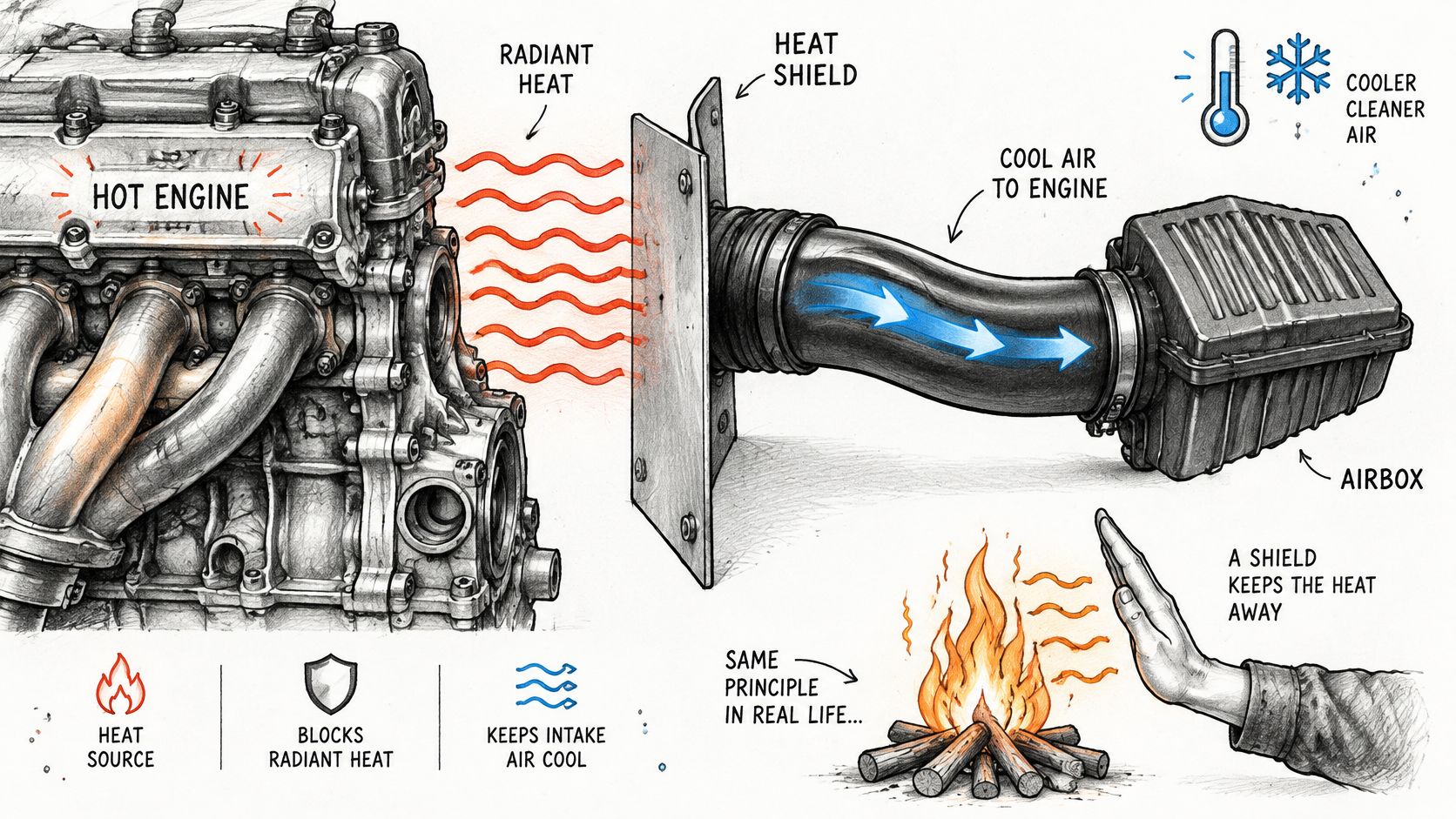
Where the Heat Comes From
In an Audi bay, the main sources are the exhaust manifolds and downpipe, the turbocharger or supercharger housing, and hot air recirculating when the car stops moving. At speed, airflow carries some of that heat away. At idle or after a pull, it doesn't, so radiant energy keeps soaking into the airbox, tube, clamps, and nearby plastic.
Heat soak gets worse after shutdown. There's no intake airflow and no cooling airflow, but exhaust hardware stays hot and keeps radiating. Your next start can therefore begin with a warm intake tract even if cruising temperatures looked acceptable minutes earlier.
What the Shield Can and Cannot Do
A good shield attacks two paths. Its reflective face rejects radiant transfer from hot hardware, and an air gap or insulating layer slows conduction into the intake. It can't stop the engine from ingesting hot bay air if the filter inlet, box seal, or ducting already pulls from that air.
Practical rule: A cooler tube proves the barrier is working on that surface. It doesn't prove cooler air is reaching the cylinders.
Manufacturers often quote surface performance, which you need to read with care. In 2024, Zircotec stated its detachable automotive heat shields can operate at temperatures up to 1000°C and achieve up to a 50% reduction in hot-to-cold surface temperatures. That's a hot-side to cold-side surface claim, not a promise that IAT falls by half.
Set your expectation there. Expect slower surface heating and better resistance to soak, then measure the air separately. Owners considering broader thermal work on the Eaton setup should also understand the limits discussed in this Audi supercharger upgrade guide, because shielding the inlet doesn't increase charge-cooler capacity.
OEM and Aftermarket Heat Shields Compared
Start with construction and clearance, not finish.
| Type | Material and design | Strength | Limit |
|---|---|---|---|
| OEM shield or insulating sleeve | Molded plastic or foil-faced sheet matched to the stock layout | Correct fit and clearance for the factory setup | Limited radiant protection and often not sized for added tuning hardware |
| Aftermarket reflective aluminum panel | Polished or foil-faced aluminum on brackets | Low cost and easy to reposition | Must be spaced off the tube, otherwise it conducts heat |
| Stainless steel shield with air gap | Thin stainless sheet on standoffs | Holds up to heat cycling and vibration | Heavier, needs careful bracket design |
| Multi-layer detachable shield | Layered metal with insulating core and removable covers | High temperature rating and easy service access | Bulkier, needs checking around the filter box |
| Thermal wrap or sleeve | Woven glass-fiber or ceramic-fiber wrap on the tube | Cuts conductive heat through the tube wall | Can trap moisture and heat if not vented |
How to Read the Choices
Choose the OEM shield or sleeve when the stock routing is unchanged and you want the lowest fitment risk. Choose a reflective aluminum panel when you need a light, adjustable barrier and you can preserve a clear gap. Choose stainless on standoffs when the shield lives close to exhaust hardware and must survive vibration and repeated heat cycles.
Choose a multi-layer detachable shield when service access matters and there's physical room around the box. Use a thermal wrap or sleeve only where a rigid panel won't clear, and inspect it for trapped moisture, fraying, and heat held against the tube after shutdown.
Temperature ratings need the same literal reading. In 2025, Heatshield Products rated its Cold Air Intake Heat Shield for up to 1100°F of continuous heat, 2000°F of intermittent heat, and direct-contact temperatures up to 500°F. Those figures describe what the material can survive. They don't tell you the temperature of air inside the tube.
Matching Type to Engine
On a supercharged EA837 car, I'd usually start with a spaced reflective panel on the hot side and leave a sound OEM sleeve where factory clearance is already good. On an EA825 RS, stainless or multi-layer shielding on standoffs suits the turbo side better. I'd reserve wrap alone for tube runs where a panel can't clear hardware.
That choice also affects the rest of the cooling package. The engineering behind the ÜberBrick factory supercharger brick conversion is a useful reminder that heat-exchanger capacity and inlet shielding solve different problems.
Fitment Checks for Audi EA837 and EA825 Intakes
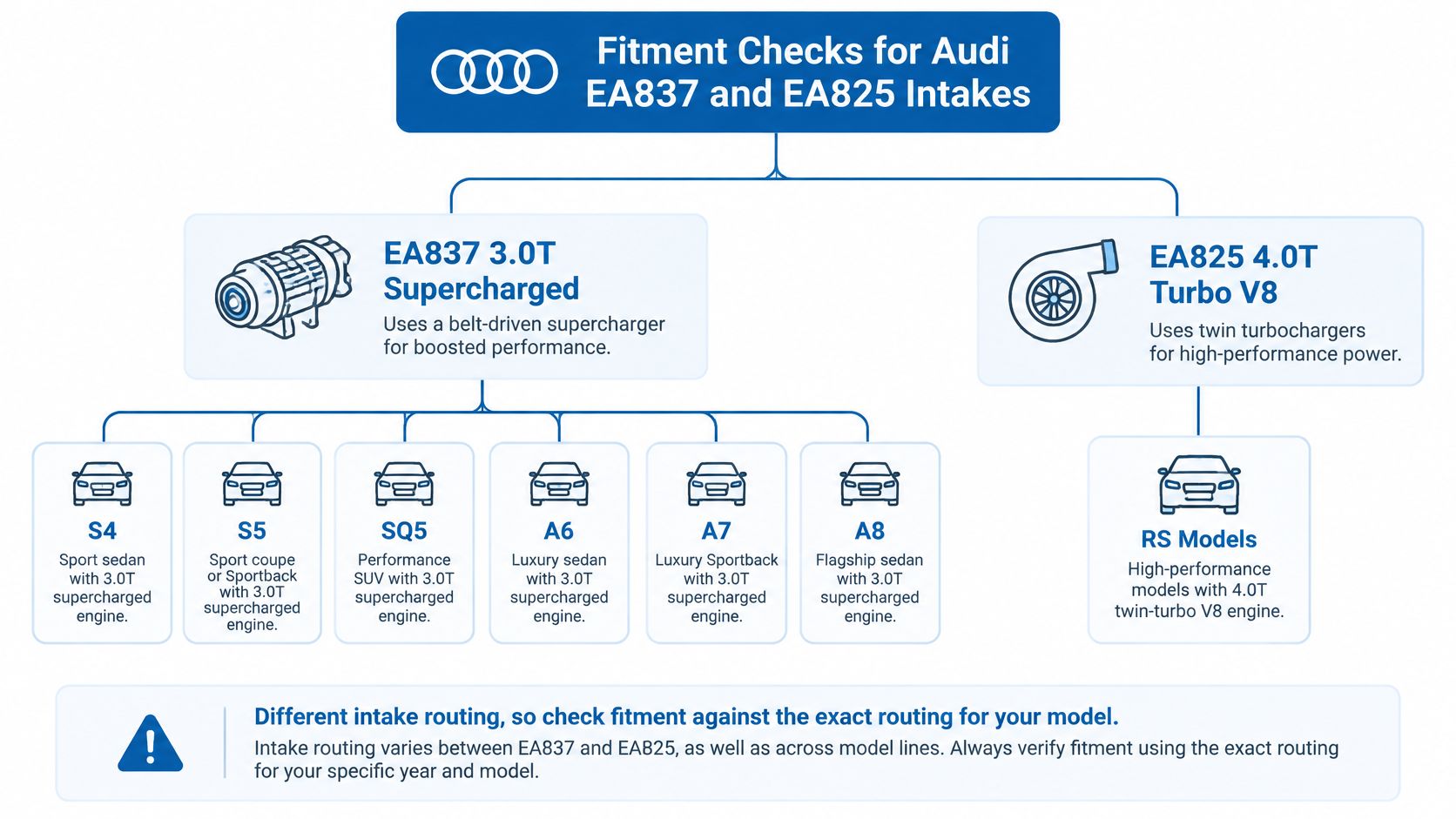
The supercharged EA837 3.0T used in S4, S5, SQ5, A6, A7, and A8 applications doesn't route its intake like the turbocharged EA825 4.0T V8 in RS models. Don't assume a shield shaped for one bay clears the other, or that model-year changes leave every bracket, hose, and box latch in the same place.
The fitment diagram below separates the two engine families before you check individual locations.
| Location | Nearby heat source | What to verify | Common conflict |
|---|---|---|---|
| Air filter box | Engine-bay air near the cowl and radiator-side airflow | Sealing to the box lid and drain path | Shield blocks the lid latch or filter access |
| Intake tube, filter to charger | Exhaust-side radiant heat and recirculated hot air | A visible air gap from the tube | Shield touches the tube and conducts heat into it |
| Supercharger or turbo inlet | Compressor housing and hot exhaust-side hardware | Clearance from boost hoses, clamps and joints | Rubs on boost hoses or couplers |
| Intercooler piping | Hard pipe heat-soaked while stopped | Room for coupler movement | Shield hides couplers and clamps from inspection |
| Downpipe and manifold side | Highest radiant source on the engine | Reflective face toward the source, no contact with exhaust wrap | Heat soaks into plastic mounts and clips |
Location by Location
At the air filter box, open and close the lid with the shield mocked up. Check the latch, filter removal path, box seal, and drain. A shield that forces the lid or blocks service will eventually get bent, left loose, or removed.
Along the intake tube, look for a continuous visible gap. The vehicle heat-shield research in this Silesian University of Technology paper identifies polished or reflective metals with emissivity below approximately 0.2 as effective radiative barriers, while glass fiber, foam, or trapped air reduces conductive transfer. Put the reflective face toward the manifold, turbocharger, or other source, and keep trapped air between shield and intake.
At the charger inlet, cycle your attention to hoses, couplers, clamp tails, and wiring. Engine movement closes small gaps, so a shield that barely clears at rest can rub under load. At intercooler piping, don't bury couplers where you can't inspect them, and don't pin a hard pipe so tightly that normal movement strains the joint.
On the downpipe and manifold side, keep the shield off exhaust wrap and away from plastic clips and mounts. Contact defeats the air gap and gives heat a direct path into parts that weren't designed to carry it.
A shield pressed onto the intake isn't insulation. It's a heat bridge.
Dry-fit everything cold before drilling or permanent mounting. For EA837 owners, the routing context in this guide to the supercharged Audi S4 helps explain why charger location makes some universal panels awkward.
What Testing Shows About Real Temperature Gains
A heat shield can cool the area around a turbo without making the intake-air sensor reading change much. In Verus Engineering's Putnam Park Road Course testing, a turbo heat shield reduced temperature around the turbo by approximately 14 to 23°F over four consecutive laps, while airbox IAT fell only about 0 to 3°F. By lap four, engine-bay temperatures began to equalize.
The difference matters when judging a shield. Surface temperature near the heat source can change clearly, while the intake sensor responds less because airflow, sensor location, duct sealing, and charge cooling all affect what it measures.
| Test or study | Measured change | Condition | Takeaway |
|---|---|---|---|
| Putnam Park track, turbo heat shield | Turbo-area temperature down about 14 to 23°F | Four consecutive laps | Surface gain near the heat source is clear |
| Putnam Park track, airbox intake-air sensor | Intake-air temperature down about 0 to 3°F | Same four laps | The sensor reading barely moves |
| Putnam Park track, lap four | Engine-bay temperatures begin to equalize | Repeated load | Gains fade under sustained heat |
| SAE under-hood study on a production vehicle | Recirculated air up to 18°C above ambient at condenser inlet | Some operating conditions | Engine-bay heat changes the intake environment |
| 2024 SUV engine-bay simulation | Inner inlet air reaches about 116 to 120°C | Post-load soak at shutdown | Shutdown heat can outweigh the shield's effect |
| 2018 SAE turbocharged intake study | Typical intake-air temperature about 30 to 70°C | Varies with load, speed and ambient | A reference range for your own readings |
How to Read the Test Numbers
The 30 to 70°C intake-air range gives context for readings that vary with load, speed, and ambient conditions. The production-vehicle study also found recirculated air up to 18°C above ambient at the condenser inlet under some conditions. After shutdown, the SUV simulation found inner inlet air around 116 to 120°C, showing how heat soak can build when airflow stops.
The 2018 SAE turbocharged intake study reported approximately 2.5% lower fuel consumption with active intake-air subcooling using an air-conditioning-based system. That result concerns active cooling, not a passive heat shield, and shouldn't be used to predict a shield's fuel or power gains.
Expect the most noticeable change near the heat source, and a smaller or negligible change at the IAT sensor. If the sensor reading stays steady, check fresh-air routing, duct sealing, sensor placement, and charge-cooler capacity before judging the reflective barrier. Measured gains from a shield are often modest, and there is no universal horsepower figure.
How to Install an Intake Heat Shield Step by Step
Work cold, mock up first, and don't make permanent holes until the shield clears everything through a full service cycle.
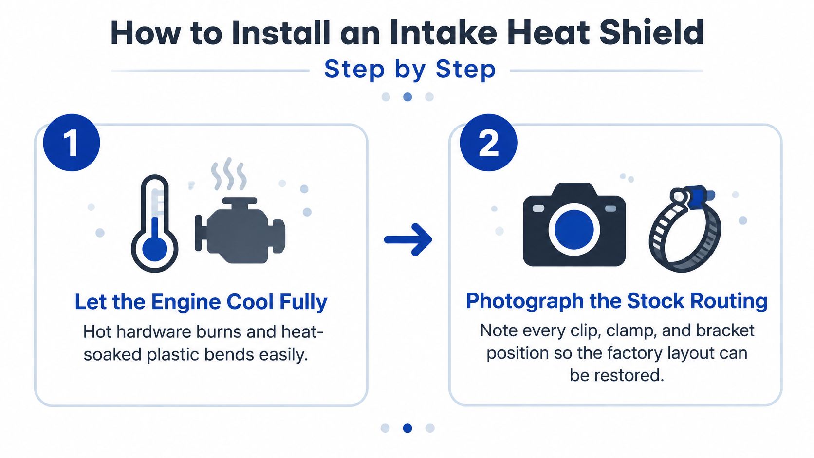
The opening steps in the process graphic focus on cooling and documenting the factory layout.
Installation Sequence
- Let the engine cool fully. Hot hardware burns, and heat-soaked plastic bends or cracks more easily. Don't judge clearances on swollen, hot components.
- Photograph the stock routing. Capture every clip, clamp orientation, bracket, hose path, and wire position. Those photos let you restore the factory layout if the shield fails testing.
- Remove only what blocks access. Take off the airbox lid and loosen intake clamps as far as needed. Pulling the whole tract apart creates extra leak and alignment risks.
- Dry test-fit with hoses in place. Hold the shield where it'll live and apply the location checks from the fitment table. Look for tube contact, hose rub, lid interference, and contact with exhaust wrap.
- Mark rigid mounting points. Use the chassis or a rigid bracket, never a flexing plastic intake as the structure. A bracket bolted to the airbox can vibrate loose and let the panel settle onto the tube, so use standoffs to hold the gap.
The video below is useful for seeing the handling and positioning before you commit to final fasteners.
- Face the reflective side toward the heat. Point it at the exhaust, turbo, or supercharger side, following the orientation rule established during fitment. A reversed multi-layer panel wastes its best surface.
- Seal bypass edges. Close open paths at the box and tube where hot bay air can slip around the barrier and reach the filter. Don't seal the intended fresh-air inlet or box drain.
- Tighten without crushing the assembly. Snug fasteners firmly, but don't flatten spacers, distort thin sheet, or crack plastic mounting ears. Recheck that standoffs still hold the intended gap.
- Reinstall and road-check. Refit the airbox and clamps, start the engine, listen for contact, then inspect after a short drive. Look for witness marks on hoses and tube surfaces, loose fasteners, and any place engine movement closed the gap.
Common slip: The shield clears in the driveway, then touches under load. The post-drive witness check catches what a static fit misses.
Verify Your Shield Before You Keep It
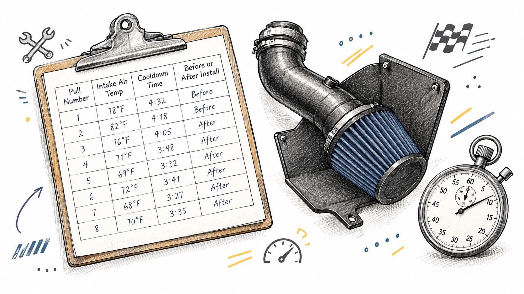
A useful comparison depends on repeatable conditions. Before installation, log a baseline on a familiar route, in similar ambient conditions, with the same cooldown and several pulls. After fitting the shield, repeat that sequence. Changing the route, soak time, or weather makes the before-and-after readings harder to compare.
Use scan-tool data for the runs, and keep a guide to intake air temperature gauges handy if you want a dedicated readout rather than relying only on scan-tool sessions.
| Measure | How to log it | What it tells you |
|---|---|---|
| Intake-air temperature | Scan-tool reading at idle and during repeated pulls | Whether readings are consistent across comparable runs |
| Ambient temperature | Same-day weather or ambient sensor reading | Whether conditions changed between runs |
| Coolant temperature | Scan-tool reading during each run | Whether engine temperature differed between comparisons |
| Heat-soak duration | Time since shutdown before each run | Whether cooldown conditions match |
| Vehicle speed | Logged during pulls and road sections | Whether the runs followed the same driving conditions |
| Ignition timing or knock correction | Logged during repeated pulls | Whether engine behavior changed during the comparison |
| Surface temperature near the shield | Infrared thermometer on tube and box | Whether the same nearby surfaces were measured each time |
Turning Readings Into a Decision
Run the same sequence at stationary idle and on the road. Record when each run begins, how long the vehicle has cooled, and whether the pulls follow the same route and speed conditions. Repeat the sequence after installation rather than judging the shield from a single reading.
Keep the shield if the readings are repeatable and it remains secure, clear of surrounding parts, and easy to service. Rework or remove it if it rubs, blocks service access, restricts the inlet, or traps heat after shutdown. If results vary between runs, repeat the comparison under more consistent conditions before deciding.
Pairing Shields with Intercooler and Charge-Air Upgrades
Start with routing and sealing, then fit the shield. Consider more cooling capacity only if logged IAT continues to climb during repeated pulls. This order helps distinguish a heat-management issue from a filter drawing engine-bay air through an unsealed box.
An upstream shield blocks radiant heat, but it cannot restore a saturated heat exchanger's capacity. The air-to-water intercooler overview explains how the cooling circuit handles charge-air heat. Use logs to guide upgrade choices, rather than judging the system by how cool a surface feels.
Where the Circuit Is Exposed
- Heat-soaked hard piping: Pipes absorb engine-bay heat while stopped and can transfer it to charge air after driving resumes.
- Couplers and clamps: Joints move under boost and engine movement. Keep shielding clear so it does not restrict movement or hide slipping and wear.
- Changed routing: If a bracket or panel shifts a pipe, leave movement room at both ends.
Where a joint needs controlled flex, a Vibrant 4 Ply Reinforced Silicone Hump Hose Connector - 2.75in I.D. x 3in long (BLACK) is designed to accommodate movement and vibration between hard pipes.
Consider heat exchanger cores or intercooler replacement when logs show charge air staying hot under sustained load, even after routing and sealing are corrected. A shield alone does not increase cooler capacity.
Use a simple decision rule: if nearby surfaces cool but IAT remains high across repeated pulls, check sealing and cooler capacity next. If IAT stabilizes and fitment is clean, stop there. The intake sensor may show little change even when surfaces near the heat source respond to the shield, so judge each reading for what it measures.
If your logs point beyond a radiant barrier, Vorsprung Autowerk offers Audi-specific cooling, intercooler, intake, and charge-piping components for EA837 and EA825 platforms, with fitment support to help match parts to your model. Visit Vorsprung Autowerk to compare options before buying another thermal upgrade.


