

A 255 LPH fuel pump isn't a horsepower rating, despite how often it appears in product titles and tuning advice. The label describes a nominal volume class under stated test conditions. Once the pump is working against rail pressure, boost-referenced pressure, wiring losses, fuel temperature, filtration, and regulator demand, the useful number can be very different.
That distinction matters on Audi EA837 3.0T and EA825 4.0T builds. A pump that looks adequate on a bench can lose pressure during a long pull, especially when voltage falls at the connector or the system requires more pressure than the test curve used for the advertised rating. The correct question isn't “How much horsepower does a 255 LPH pump support?” It's “How much fuel will it deliver at my actual pressure and loaded voltage?”
Table of Contents
- Why 255 LPH Is a Starting Point, Not a Horsepower Number
- How Pressure and Voltage Change Real Pump Output
- Sizing a 255 LPH Pump to Your Target Horsepower
- Wiring and Fuel Pressure Considerations for an Audi Install
- Install Walkthrough From Tank Prep to First Start
- Troubleshooting Pressure Drops and Lean Conditions
- Ethanol Compatibility and Final Decision Checklist
Why 255 LPH Is a Starting Point, Not a Horsepower Number
A 255 LPH fuel pump is a flow-class rating, not a horsepower promise. Under specified test conditions, the label represents approximately 255 liters per hour, or about 67.4 U.S. gallons per hour. That figure helps compare pumps in the same class, but it does not show how much fuel reaches the injectors in a modified Audi.
Ford Performance's fuel-system sizing guidance shows why a simple horsepower conversion fails. The method converts volume into fuel mass, applies a usable-capacity factor, then checks the result against engine fuel consumption. In its published example, a 255 L/hr pump is treated as approximately 405 lb/hr. Applying a 90% usable-capacity factor produces about 364 lb/hr, which under those assumptions can support approximately 720 naturally aspirated flywheel horsepower.
That figure describes the example, not every EA837 or EA825 installation. The guidance also requires at least 39.15 psi across the injector at every engine speed and load. An Audi running boost faces different pressure and consumption demands, while fuel type, injector pressure, voltage, regulator design, duty cycle, and control strategy further change the result.
Practical rule: Read “255” as a flow-class label. Use the pump curve at your actual pressure and loaded voltage to judge capacity.
Size the system around its hardest operating condition: maximum load, full boost, the intended fuel blend, and the highest pressure commanded by the regulator or controller. A pump that cannot hold rail pressure in that condition is undersized, regardless of its free-flow label. Bench flow and catalog horsepower claims cannot replace a pressure test on the car.
How Pressure and Voltage Change Real Pump Output
A 255 LPH fuel pump does not deliver 255 LPH at every operating point. Its label describes a flow class measured under a stated test condition. As rail pressure rises, available flow falls. On a boosted Audi, that pressure demand can increase while the engine also requires more fuel, so free-flow numbers are a poor sizing reference.
A Saab fuel-system engineering guide documents a variable-speed pump rated near 255 LPH at roughly 40 psi. At 70 psi, the same pump delivers approximately 208 LPH, or about 55 gallons per hour, reducing output by about 18.4% from the headline rating. The guide also reports maximum pump speed at approximately 95% commanded duty cycle. If rail pressure drops at that point, the pump cannot maintain the required delivery. The published Saab pump guide documents the pressure relationship and duty-cycle behavior.
A separate 255 LPH replacement-pump listing gives 255 LPH at 43 psi and 190 LPH at 80 psi, a decline of approximately 25.5%. Those figures are not interchangeable with the Saab data because pump design, voltage, fuel temperature, and test procedure differ. They show the same practical rule: compare pumps at the pressure the car sees, not at a free-flow test point.
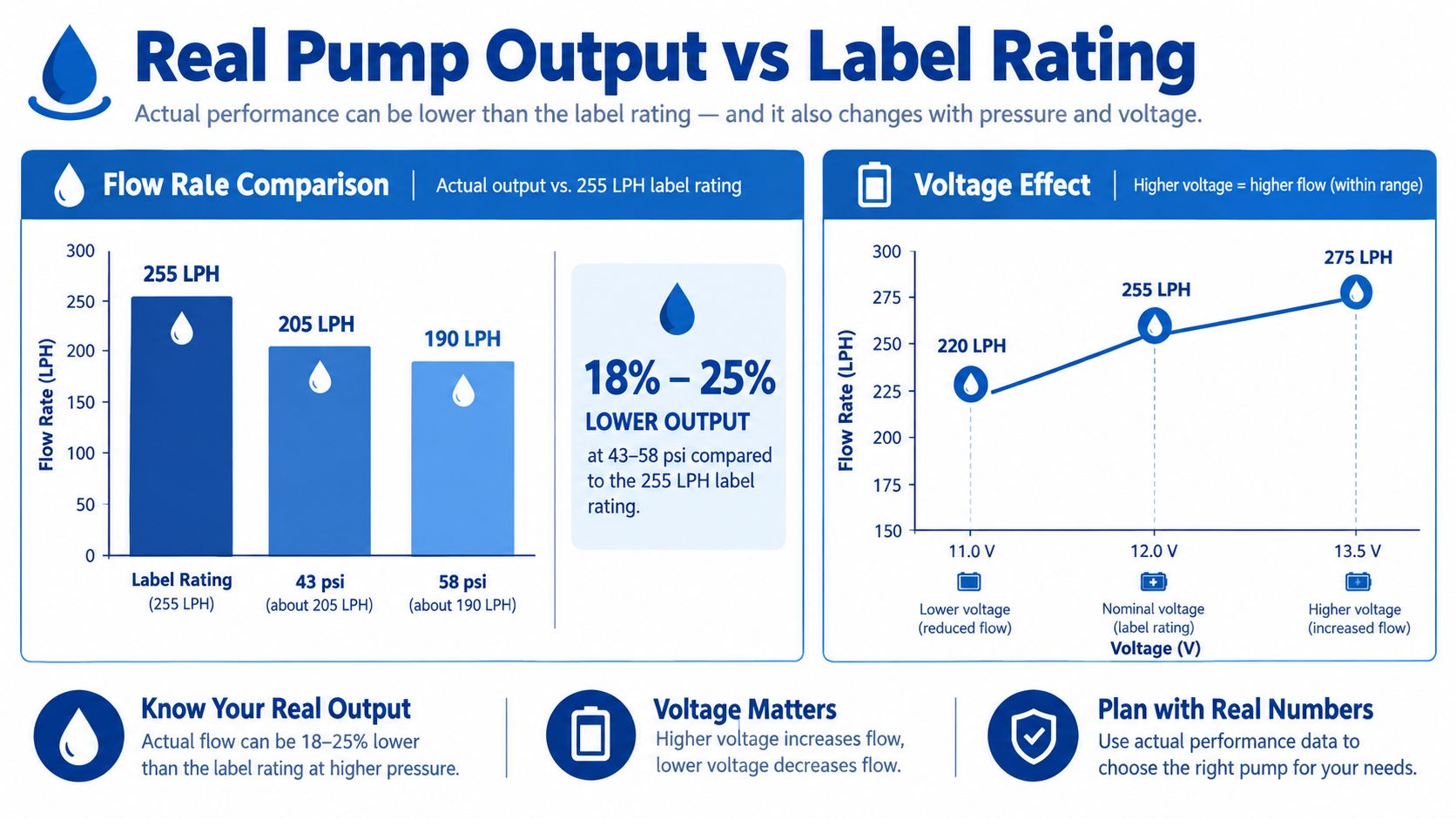
Voltage is part of the pump specification
Electrical supply directly affects pump speed and output. A published test of a nominal 255 LPH unit recorded 261 LPH at 45 psi and 228 LPH at 60 psi, while current increased from 10.9 A to 11.5 A at the same voltage. The comparison is useful because it pairs fuel pressure with electrical load. Use the 255 LPH pump test and installation reference when checking how the pump behaves under pressure.
Measure voltage at the pump connector while the pump is operating, not only at the battery. Supply voltage should generally remain within about 0.5 V of system voltage. A tired relay, undersized feed, corroded ground, overheated hanger connector, or damaged terminal can make a healthy pump appear undersized.
In-tank replacement versus lift-pump arrangement
A higher-flow in-tank pump keeps the fuel path simple and usually suits the packaging of the EA837 or EA825 tank module. It can work well on a stock-turbo car or moderate build when the loaded pump curve, pressure target, and fuel compatibility match. The trade-off is sustained high duty cycle, which increases electrical load and heat inside the tank.
A lift-pump-plus-factory arrangement separates tank transfer from high-pressure delivery. That layout can suit a larger turbo build or repeated high-load use, but it adds control hardware, plumbing, packaging demands, and failure points. Return-style and returnless systems also behave differently. A return-style system sends excess fuel back to the tank, while a returnless arrangement may regulate delivery through module control and pressure management.
Fuel choice changes the decision. A pump validated for gasoline is not automatically suitable for higher alcohol blends. Check the complete fuel path, including the tank sock, wiring, connectors, hoses, regulator, and seals. Select the pump from its loaded flow curve at the intended pressure and voltage, not from the number printed on the box.
Sizing a 255 LPH Pump to Your Target Horsepower
A 255 LPH label is a flow class, not a horsepower promise. Size the pump from the fuel volume available at maximum rail pressure and operating voltage, then convert that flow into mass for the fuel in the tank. Leave capacity for voltage sag, fuel temperature, filter restriction, and pump wear.
Start with the pressure the system must hold under full load. Read the pump's flow curve at that pressure, not at its headline rating, and use the voltage measured at the pump connector while it is running. A pump that looks adequate on a bench can fall short once boost raises the required pressure or wiring losses reduce motor speed.
Apply the Ford volume-to-mass method introduced earlier to the loaded pressure and measured voltage, without repeating the PDF citation here. The result should be checked against injector demand, duty cycle, fuel type, and the engine's actual operating conditions. Do not transfer a naturally aspirated example directly to a boosted EA837 or EA825 using a different fuel and pressure strategy.
Use the comparison below as a calculation framework, not as universal horsepower brackets. Pump output, fuel density, injector demand, rail pressure, and engine configuration all affect the result.
| Fuel | Approx. usable flow | Typical power bracket |
|---|---|---|
| E10 or pump gasoline | Use the pump curve at loaded pressure, then convert volume to mass flow | Depends on pressure, injector demand, and engine configuration |
| E85 or higher ethanol blend | Use fuel-specific mass conversion and verify explicit pump compatibility | Requires more careful capacity and material validation |
| Race-style fuel | Use the fuel supplier's density and the pump's loaded curve | Must be calculated for the specific engine and tune |
Injector sizing must agree with the same inputs. Flow rating, fuel pressure, duty cycle, and fuel composition all affect the required pump capacity. The guide to 550 cc Bosch injectors provides a useful reference, but larger injectors cannot correct a pump that loses pressure at full load.
A lift pump may suit a build where the factory arrangement becomes the restriction. It is not automatically better than a correctly sized in-tank upgrade. On a stock-turbo EA837 running gasoline, a verified in-tank pump may keep the system simpler. On a high-boost EA825 or ethanol build, choose from the complete pressure-versus-flow result rather than the pump category.
Wiring and Fuel Pressure Considerations for an Audi Install
A pump upgrade needs a sound electrical path. The usual weak points are the factory connector, hanger wiring, relay contacts, ground path, and voltage drop between the battery and pump. A pump can be mechanically capable yet fail to deliver because the motor never receives the voltage it needs.
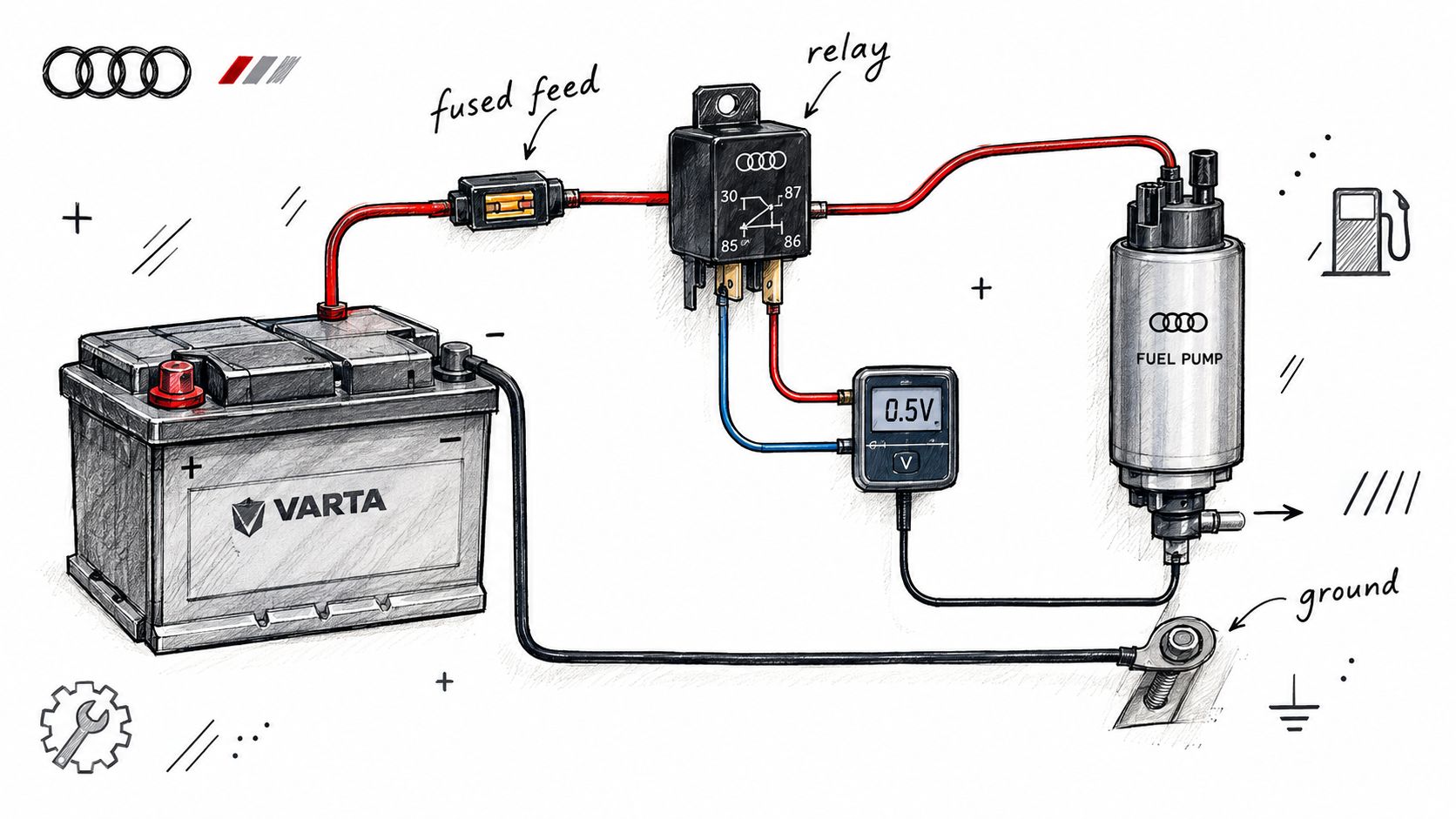
Use a dedicated fused feed and a properly controlled relay when the upgraded pump's current demand exceeds what the original circuit was designed to handle. Check the positive-side voltage drop from the supply to the pump connector, then check the ground-side drop from the pump ground back to the battery ground. Perform both tests with the pump running, not with an unloaded continuity check.
Technician guidance flags more than 0.2 V of voltage drop as capable of affecting operation, and the pump supply should generally remain within about 0.5 V of system voltage. The Reflex 0-10 bar pressure sensor can also support pressure logging where the vehicle's control and tuning setup accepts an external sensor.
Match the regulator to the fuel system
A regulator determines the pressure the pump must overcome. In a return-style arrangement, the pump may deliver more fuel than the engine consumes, with the regulator returning the excess to the tank. That can improve temperature management and make pressure control more predictable, but the return path, regulator, and tank plumbing must all support the intended flow.
A returnless system relies more heavily on module control and pressure management. Don't assume a pump swap alone changes the system's pressure capability. Confirm base pressure, pressure under boost, and the regulator's behavior before deciding whether the pump is at fault.
After the electrical checks, perform a pressure test under the conditions that matter. Watch pressure, pump voltage, current, and commanded duty cycle together. A pressure drop with stable voltage points toward capacity, restriction, or control strategy. A pressure drop that appears with voltage loss points first toward wiring.
For a visual reference on pressure and electrical testing, use the following installation resource after setting up the gauge and meter:
Install Walkthrough From Tank Prep to First Start
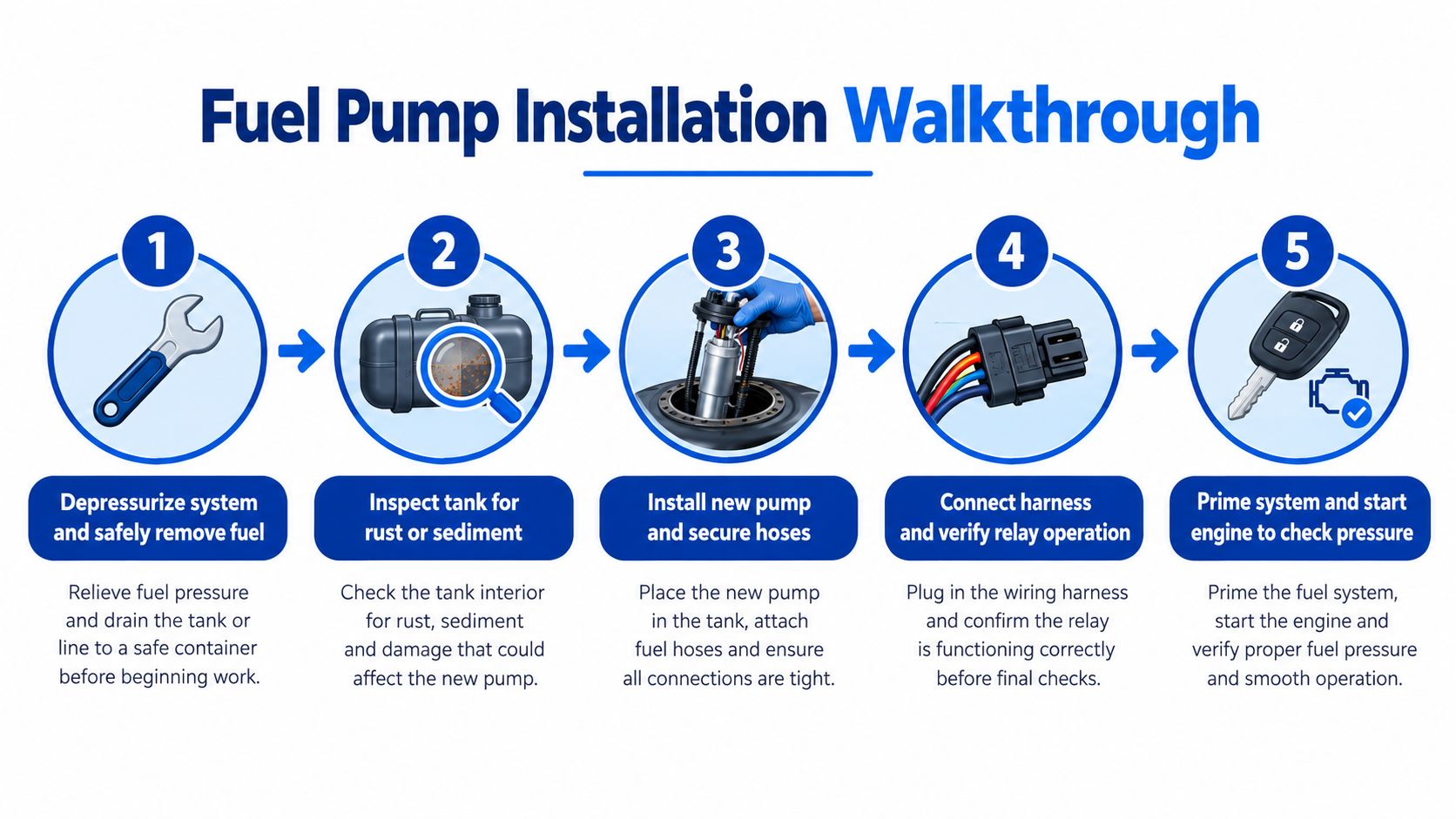
Fuel-system work starts with safety, not parts removal. Depressurize the system, remove fuel safely, ventilate the work area, and keep ignition sources away. The tank condition determines whether the new pump has a fair chance of surviving.
Prepare the tank and module
Inspect the tank for rust, sediment, and loose contamination before fitting the replacement. Clean the tank as needed, and clean or replace the strainer. Contamination is identified as the leading cause of in-tank electric-pump failures in technician guidance, while one manufacturer training document attributes 20% of pump product failures to contaminated fuel in this fuel-pump failure reference.
Examine the hanger connector and pump-to-hanger wiring closely. Heat discoloration, loose terminals, corrosion, or melted plastic are reasons to repair the circuit rather than install a new motor into the same damaged connection. A replacement pump won't fix a terminal that can't carry current.
Use a fuel-pump installation connector kit when the existing connector shows heat damage or poor terminal tension. Secure the pump, hoses, clamps, and strainer so the inlet can't pull against the tank floor or draw debris.
Prime before judging the repair
Reconnect the module, prime the system, and watch how quickly pressure rises. Check for leaks before starting the engine. Once running, verify operating pressure and electrical supply at the pump.
After shutdown, check residual pressure. Rapid loss can point to a leaking pump check valve, regulator, injector, or connection. Don't dismiss a slow pressure rise or immediate pressure loss as normal until each part of the system has been considered.
Troubleshooting Pressure Drops and Lean Conditions
A lean condition under load does not automatically condemn a new 255 LPH pump. On tuned Audi platforms, the same symptom can come from a weak ground, restricted strainer or filter, regulator fault, wiring resistance, or contamination that has harmed the replacement pump.
Connect a calibrated pressure gauge at the rail or an approved test port. Record key-on pressure, idle pressure, and pressure during load. Measure voltage at the pump connector while the pump is running. A continuity check with the circuit unloaded cannot show resistance that appears only when current is flowing.
Use a volume test as a second opinion
Route fuel safely into a calibrated container and perform a timed delivery test. A useful shop benchmark is at least 1 pint in 15 seconds, equivalent to approximately 1.9 lpm or 114 lph. Use that figure as a general reference, while the vehicle manufacturer's specification takes priority.
Repeat the test under relevant pressure. A pump can pass a free-flow check yet fall short at rail pressure. If the timed volume passes with the system unloaded but pressure drops during a high-load pull, compare the loaded pump curve with measured voltage, filter condition, regulator operation, and control duty cycle.
Injector faults can produce similar lean behavior. If pressure and voltage remain stable but fueling is uneven, inspect injector flow and spray quality. Ultrasonic injector cleaning can help determine whether the injectors contribute to the fault, but cleaning cannot correct inadequate pump delivery.
Diagnostic rule: A pressure drop with adequate voltage does not prove pump failure. It may indicate insufficient capacity, a restriction, or a control problem.
Check the return path on return-style systems and confirm that the regulator responds correctly. Inspect the strainer for debris, too. A replacement pump installed in a contaminated tank can reproduce the original complaint, while low voltage can make a correctly sized pump deliver like a smaller unit. Record pressure and voltage during the same loaded event, then diagnose the component that fails under those conditions.
Ethanol Compatibility and Final Decision Checklist
Ethanol compatibility is a durability and sizing question, not a marketing checkbox. Higher alcohol blends can place different demands on pump internals, seals, wiring connections, and regulators. They also require greater fuel volume for the same engine power because their energy density is lower.
Before ordering a 255 LPH fuel pump for an EA837 or EA825, answer four questions:
- Blend rating: Is the specific pump explicitly validated for the fuel you intend to run, rather than merely described as a performance replacement?
- System compatibility: Are the tank sock, hanger wiring, connector, hoses, seals, regulator, and return path suitable for that blend?
- Test fuel: Was the published flow curve measured with gasoline, ethanol, or another fuel?
- Loaded delivery: What flow remains at your actual rail pressure and the voltage measured at the pump connector?
Market data illustrates why buyers should ask these questions. One forecast projects the ethanol and biofuels category to grow at 9.4% annually, from approximately $1.6 billion in 2025 to $3.9 billion by 2035, as reported in this automotive fuel-transfer-pump market analysis. A separate industry source in that research reports that roughly 15% of pump designs released during 2023 to 2025 were engineered for higher ethanol, biodiesel, or e-fuel blends. Those figures don't validate any individual pump, but they reinforce that compatibility isn't universal.
The final workshop checklist
- Confirm pressure: Measure rail pressure at maximum load, not just key-on or idle.
- Read the curve: Use the manufacturer's flow data at that pressure and loaded voltage.
- Verify voltage: Test at the pump connector while operating and inspect the ground path.
- Check the complete module: Include the strainer, filter, hanger, regulator, hoses, and return path.
- Match the fuel: Verify explicit compatibility with gasoline or the intended ethanol blend.
- Leave reserve: Account for voltage sag, fuel temperature, restriction, aging, and duty-cycle limits.
- Log the pull: Record pressure, voltage, current, and delivered volume together.
An ethanol content sensor can help a compatible tuning strategy account for changing fuel content, but it doesn't replace pump sizing or electrical validation. The right decision is the pump that maintains required pressure and volume in the complete Audi system, not the one with the most convincing label.
For platform-specific Audi fueling parts, wiring components, sensors, and installation support, Vorsprung Autowerk focuses on EA837 and EA825 performance applications. Visit Vorsprung Autowerk to match the pump and supporting hardware to your Audi's pressure, voltage, and fuel requirements before you install.


