

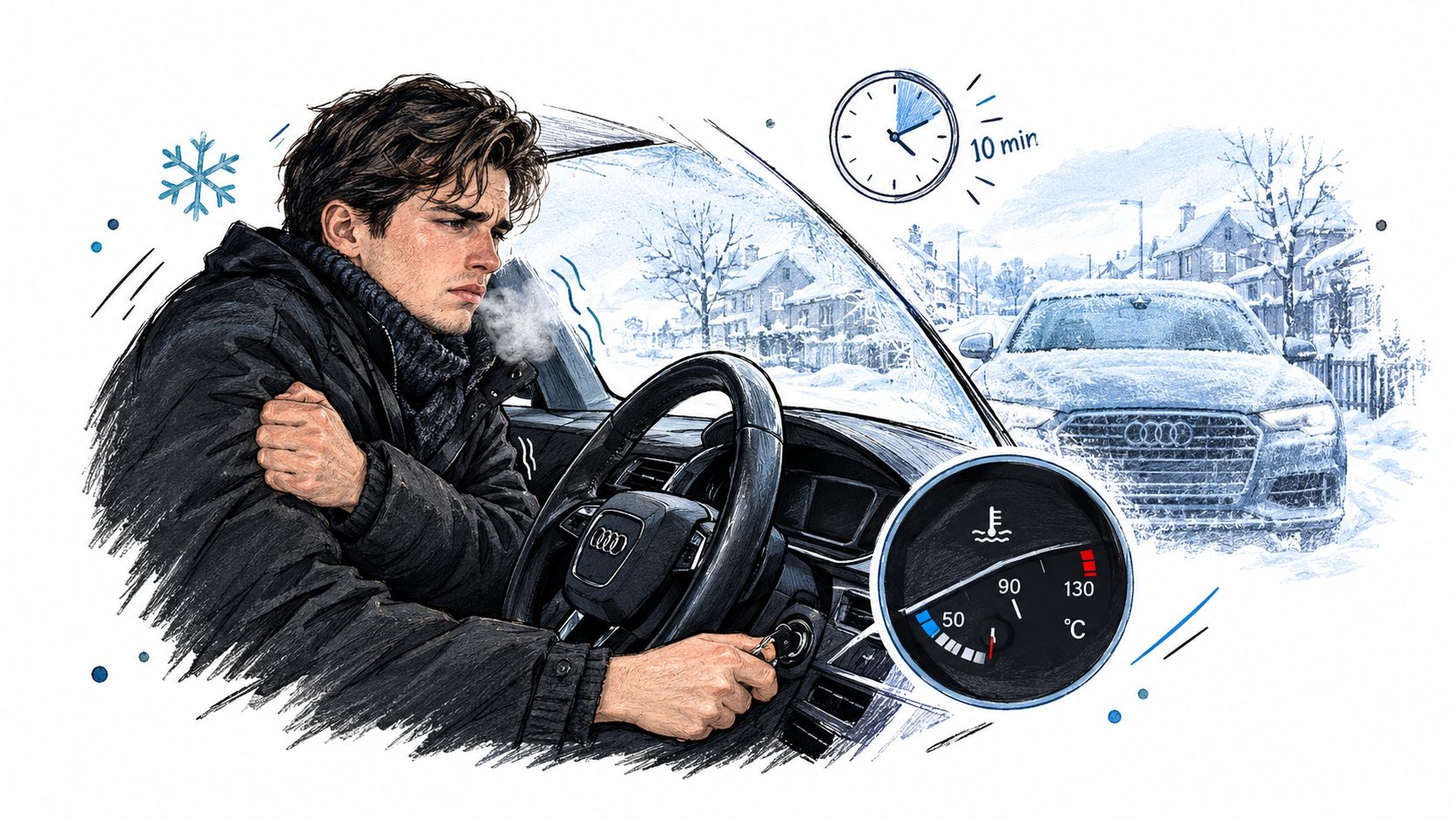
It's a cold morning, and your Audi's temperature gauge is taking its time while the heater blows air that's barely warm. You may be thinking thermostat, but a coolant control valve can create the same frustration. It doesn't let coolant through or hold it back. It routes flow through a larger thermal system, and a fault in the valve, its wiring, or the cooling circuit can leave the whole car behaving strangely.
On EA837 3.0T and EA825 4.0T cars, a sound diagnosis means looking beyond the part itself. The valve's command, position feedback, coolant temperatures, connector condition, and the system's bleeding all matter. Replace it before checking those, and you may fix the wrong problem.
Table of Contents
- The Valve Most Audi Owners Never Think About
- How an Electronic Coolant Control Valve Actually Works
- Where the Valve Sits Inside the Audi Thermal System
- Failure Modes and What They Actually Feel Like
- Diagnosing the Valve Before You Replace It
- Choosing a Replacement and Doing the Job Right
- Proving the Fix With a Post-Install Data Log
The Valve Most Audi Owners Never Think About
On a B8.5 S4 or C7 RS7, a slow warm-up and a cold cabin on a winter drive feel like familiar thermostat symptoms. But the coolant control valve may be deciding where coolant flows while the engine is still warming. It can route coolant among the engine, radiator, heater core, oil cooler, and bypass passages, so the symptom depends on which path isn't behaving as commanded.
That makes the valve a traffic cop, not a simple gate. During a cold start, the system can limit flow through the radiator to reduce heat loss. As operating conditions change, it can send flow where the engine needs it. That routing affects warm-up, cabin heat, oil temperature, and how the cooling system responds under load.
Audi's move toward this kind of active coolant distribution has been developing for decades. A U.S. patent application filed on November 28, 2001, described replacing a conventional radiator thermostat and heater valve with a design that controlled coolant distribution across multiple paths. The invention was published as U.S. Patent 6,688,333 B2 on February 14, 2003, establishing an early milestone in multi-path thermal management (U.S. Patent 6,688,333 B2).
That history matters at the service bay. If the heater stays cold or warm-up drags, the valve may be sticking, but so may an actuator, a connector, or a coolant passage. The gauge alone can't tell you which.
Practical rule: Treat slow warm-up as a cooling-system symptom, not proof that the thermostat or valve is the failed part.
How an Electronic Coolant Control Valve Actually Works
Think of the valve as a rotating junction in a plumbing network. Coolant enters, and a motor or stepper moves the internal element to apportion flow through different outlets. Depending on the design, those destinations include the radiator, radiator bypass, heater core, and oil cooler. It meters thermal flow rather than choosing between open and closed.
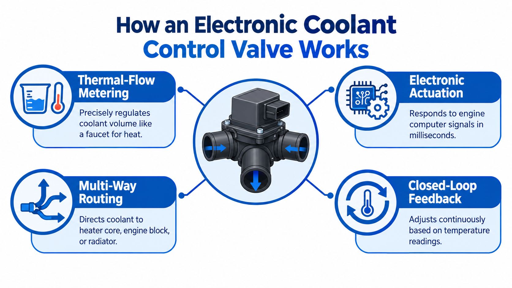
The engine computer commands a position to support the current operating conditions. At cold start, reducing radiator flow limits heat rejection. In normal driving, the valve can balance flow to maintain temperature while supplying cabin heat. Under higher load, it can direct more coolant through the radiator or oil-cooling branch. The exact strategy depends on the vehicle's hardware and calibration.
On electronically actuated systems, the ECU's command and the valve's position feedback form a control loop. The computer requests a position, the actuator moves, and feedback helps it determine whether the response matches the request. That's why a resistance check alone is weak evidence: an electrically sound motor can still fail to move a contaminated or mechanically jammed valve.
Research on active engine cooling describes electronic valves used with controllable water pumps to reduce cold-start warm-up time, with potential fuel and emissions benefits as the engine reaches efficient operating conditions sooner (coolant-distribution control patent). In practice, diagnosis should compare commanded and actual position, then check whether coolant temperatures in the connected circuits respond in the expected direction.
There's a delay between movement and temperature change. Coolant has to travel through the water jacket and heat exchangers before a sensor registers the effect. SAE testing of an electronically controlled multi-way valve used sensors at the engine water-jacket inlet and outlet to account for that transport delay. The study also reported test-specific temperature-tracking error of 0.175 K, warm-up time of 363.9 seconds, and instantaneous power consumption of 24.31 W. Those are experimental results, not Audi specifications (SAE coolant-valve control study).
Where the Valve Sits Inside the Audi Thermal System
The valve belongs to a network, and that network can include more than the engine radiator. A performance Audi may have an engine-cooling circuit, a cabin-heating circuit, a charge-air cooling circuit, and separate transmission or oil-cooling hardware. Don't assume that every part uses the same coolant or responds to the same valve command. Trace the actual hose routing and circuit design for the car in front of you.
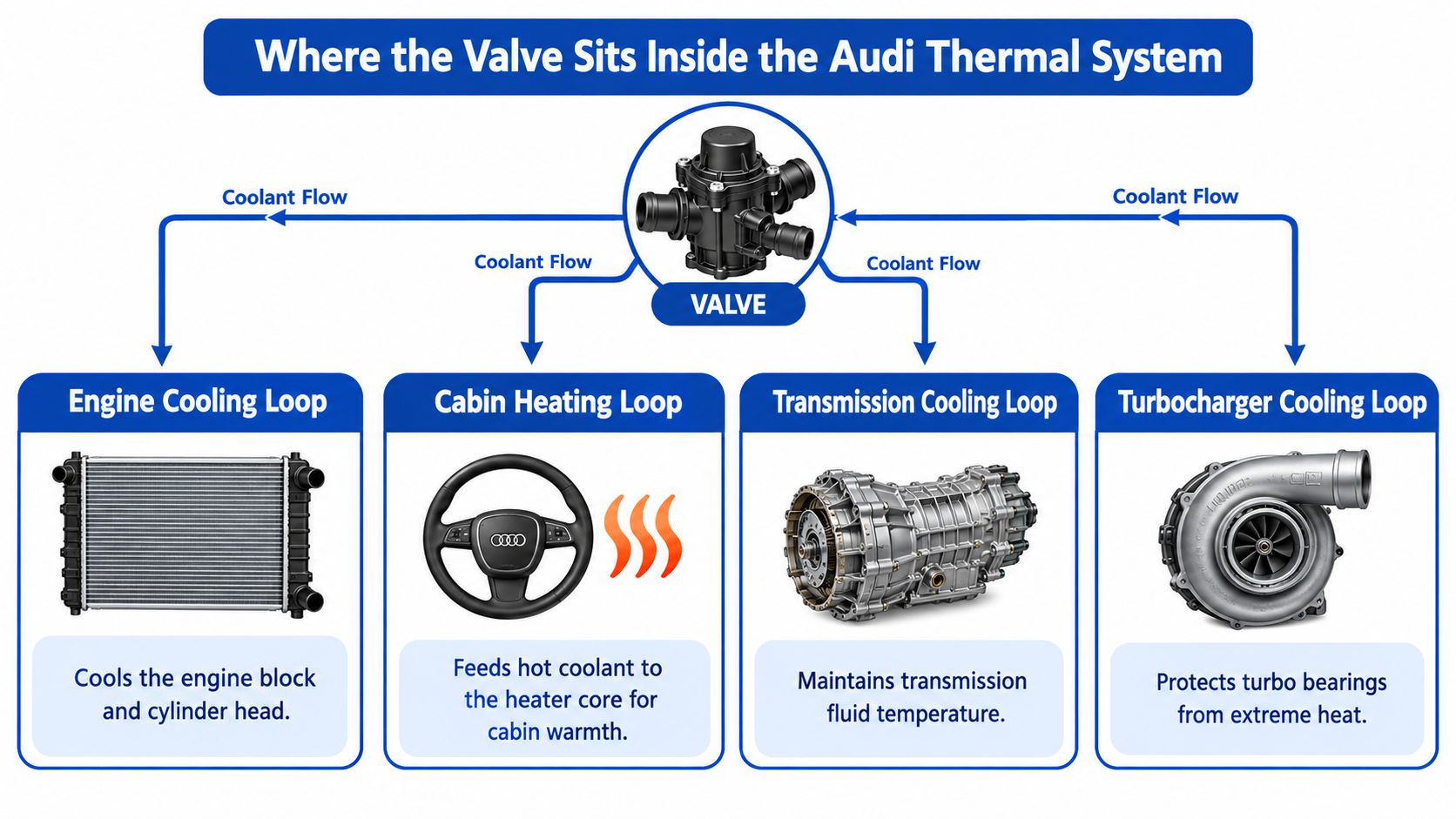
On a supercharged EA837, the charge-air intercooler circuit is a key part of repeated-pull performance. A larger heat exchanger, such as a GP Ice-style unit, can help manage heat in that circuit, while upgraded intercooler bricks such as the ÜberBrick or Großartig address heat transfer at the supercharger. Those components don't automatically increase engine-radiator capacity or correct a cabin-heating fault. A cooling upgrade can help one loop while leaving another unchanged.
The water pump matters too. An upgraded pump such as the VWA-100 changes circulation characteristics in the circuit it serves, while revised hose routing or added hardware can change flow resistance and timing. The ECU still expects the coolant temperatures and actuator responses associated with the vehicle's control strategy. A modification that alters those relationships can make a correct valve command appear ineffective, or expose an air pocket or restriction that wasn't obvious before.
A bigger heat exchanger can help repeated-pull temperature stability in its circuit. It can't compensate for an incorrectly bled system or an unintended flow path.
When planning or diagnosing a supercharger cooling change, follow the circuit from pump to brick to heat exchanger and back. The ÜberBrick development overview offers context for how that hardware fits into the broader cooling picture. The service principle is the same whether parts are stock or modified: identify the loop, confirm its flow, and then check how the valve strategy interacts with it.
Failure Modes and What They Actually Feel Like
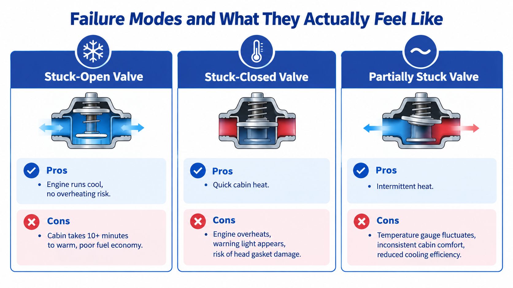
A valve fault doesn't produce one universal symptom. The flow path that fails determines what the driver notices, and more than one failure can feel like a weak thermostat.
When the valve stays open
If the valve lets too much coolant reach the radiator during warm-up, the engine may take longer to reach operating temperature. The cabin can stay lukewarm, especially on short trips, and the oil takes longer to warm along with the coolant. That pattern can point toward a valve stuck partly open, but it doesn't prove the valve is at fault. A sensor error, incorrect coolant level, or other flow problem can produce overlapping clues.
When flow is blocked or misrouted
A valve stuck closed, or directing flow away from the circuit that needs it, can leave a local area too hot even if the radiator and pump appear serviceable. The gauge may climb under load, cabin heat may become inconsistent, or the vehicle may set related faults. On a performance car, don't keep repeating hard pulls to see whether the warning comes back. Establish which circuit is losing flow first.
When the electronics pass but the valve doesn't move
This is the trap that catches parts-cannon repairs. The actuator may have plausible electrical readings and respond to a command, yet debris can stop the valve element from moving freely. A manufacturer service bulletin documents stuck-open and stuck-closed codes on a three-way coolant valve caused by debris in coolant passages after machining. The bulletin also notes that electric driving could be disabled while gasoline operation remained available. That specific document isn't an Audi diagnosis, but it demonstrates why an electrically valid actuator doesn't rule out mechanical restriction (manufacturer coolant-valve bulletin).
On EA837 and EA825 cars, avoid diagnosing by symptom alone. A slow warm-up might be a valve issue; overheating might be a circulation issue; intermittent cabin heat might involve air in the system. If there's coolant loss or evidence of leakage, inspect the area around the valve and related connections rather than assuming the valve's internal mechanism is the only suspect. This Audi 3.0T coolant-leak guide is a useful reference point for keeping leaks in the diagnostic picture.
Diagnosing the Valve Before You Replace It
A scan tool, pressure tester, and infrared thermometer can help separate a failed valve from a wiring fault or a circuit problem. Start with recorded evidence. Clear codes only after saving them, and note whether the fault returns under the same conditions.
Start with live data
Read the valve's commanded position and actual position feedback if available. Capture coolant temperature readings at the engine inlet and outlet, pump duty, fan command, and intake-air temperature. Check whether sensor readings are plausible before using them to judge the valve. If inlet and outlet temperatures diverge unexpectedly, consider a restriction, air pocket, or circulation problem rather than treating one reading as the whole story.
Check pressure, connector, and harness
Pressure-test the system using the correct service procedure, then inspect the valve connector closely. Dried coolant residue inside the connector or along the harness can point to coolant migration. Manufacturer service documentation for valves including N82, N509, and N488 warns that coolant can leak through the valve, travel into the connector and wiring, and reach connected control units. That's why a valve replacement alone may leave the underlying electrical problem untouched.
Command the valve and watch the response
Check actuator power and ground, then use a scan-tool output test to sweep the valve through commanded positions. Log position feedback and observe temperatures at the relevant circuit locations. Because coolant temperature responds after flow changes rather than instantly, compare the direction and progression of the readings, not just the first moment after a command.
Don't authorize the part on a resistance check alone. Confirm whether the valve moves, whether its feedback agrees, and whether the circuit temperatures react plausibly.
Only move to replacement when the command, feedback, wiring inspection, and temperature response point to a mechanical jam or a confirmed position error. If the warning light is the only clue, the check-engine-light diagnostic guide can help frame the broader fault-finding process, but scan data from the actual car should drive the decision.
Choosing a Replacement and Doing the Job Right
Once diagnosis points to the valve, match the replacement to the vehicle by VIN and part number. Connector style and application matter more than broad claims that a part fits an engine family. EA837 and EA825 fitment can vary, so confirm the exact assembly and compare the electrical connection and hose arrangement before ordering.
OEM and reputable aftermarket parts can both be appropriate when the application is correct. A used valve is a gamble: it has already spent time in a hot coolant stream and may carry the same contamination or mechanical wear that caused the original fault. If the old unit shows debris or sludge, find the source before fitting another valve into the same coolant.
During installation, replace seals and gaskets specified by the service procedure. Use the vehicle-specific torque values and bleeding instructions rather than guessing. Trapped air can interrupt circulation and create symptoms that look like a failed pump or valve after the repair. Don't run the engine hard until the system has been properly filled, bled, and checked for leaks.
Coolant type matters as well. Use the specification required for the car, and don't mix products based on color alone. The Audi G 13 coolant guide is a helpful reference, but the vehicle's service information remains the authority for the exact application.
After installing an upgraded pump, heat exchanger, or intercooler component, inspect the modified circuit for correct hose routing and proper bleeding. Don't assume a new valve needs adaptation, or that every Audi uses the same relearn procedure. Check the service information for the specific vehicle, then verify commanded position, temperature response, pump operation, and heater output before returning the car to normal use.
Proving the Fix With a Post-Install Data Log
A repair isn't proven because the warning light stayed off on the drive around the block. Log the system under repeatable conditions and compare the valve's command with its feedback, while watching temperatures across the circuits the repair affects. A healthy result is a plausible, consistent response, not necessarily an instantly matching temperature reading.
Use a checklist that fits the fault and the hardware:
- Valve position: Record commanded position and feedback during a controlled sweep. They should track without unexplained disagreement.
- Coolant temperatures: Compare available inlet and outlet readings as the system warms and under load. A sudden or persistent mismatch needs an explanation.
- Pump and fans: Log pump command and fan behavior alongside the temperatures, so a valve issue isn't confused with a separate circulation or heat-rejection problem.
- Modified circuits: On a car with cooling upgrades, include intake-air temperature during repeatable driving conditions. Check that the system behaves consistently after the work, not just that one sensor looks better.
A slow or erratic response can point back to an air pocket, restriction, wiring fault, or valve that isn't moving as requested. A log can't replace inspection, but it helps distinguish those possibilities and gives the next technician useful evidence. For upgrades, the heat-exchanger upgrade guide can help owners consider the hardware in the context of the wider cooling system.
Thermal management is increasingly coordinated across multiple loops, including motor, battery, and inverter circuits in electrified vehicles. If you're modifying an Audi, plan for valve strategy, bleeding, and data verification as part of the build, not as an afterthought.
Vorsprung Autowerk develops and supplies Audi-focused performance parts, maintenance components, and cooling upgrades for platforms including the EA837 and EA825. If you're diagnosing a coolant control valve or planning a cooling-system upgrade, visit Vorsprung Autowerk to explore the parts and support available for your Audi.


