

You've swapped the coil, cleared the code, and the Audi still stumbles when it's hot. The misfire may stay on the same cylinder even after the coil moves, while a cold voltage check looks normal. That pattern deserves a closer look at the ignition coil connector, its terminals, and the wiring feeding it, before another coil goes into the parts pile.
On EA837 3.0T and EA825 4.0T engines, access can be awkward, and heat and vibration put the coil harness under real stress. The connector isn't just a plastic plug. It has to hold its terminals firmly, maintain the correct electrical connections, and keep contamination out. A systematic check can separate a connector or harness fault from a failed coil, without treating every misfire as a coil-replacement job.
Table of Contents
- Why the Connector Deserves Blame Before the Coil
- Symptoms and Visual Checks Before You Touch a Meter
- Connector Pinouts and EA837 EA825 Fitment Differences
- Testing the Connector with a Multimeter
- Coil Swap or Connector Repair Decision Tree
- Replacing the Connector and Securing the Repair
- Misfires That Linger and Platform-Specific Traps
Why the Connector Deserves Blame Before the Coil
A familiar shop pattern goes like this: a cylinder misfires, someone swaps its coil with a neighboring one, and the same cylinder continues to misfire. A supply check at the connector looks fine with the engine cold. The fault returns after a heat soak or during a drive, when vibration and electrical load expose a weak terminal grip or damaged wire.
That result doesn't automatically condemn the connector, but it changes the order of suspicion. A coil that's moved to another cylinder should generally take its fault with it if the coil itself is the cause. When the misfire stays put, inspect the connector, terminal fit, harness, spark plug, and control circuit before buying another coil.
Why packaging raises the stakes
The EA837's supercharged V6 packaging can make coil access a job in itself, especially around the intake manifold. On the EA825 V8, the coils sit in tight quarters between the cam covers. In either case, cramped access can tempt a quick reconnect or a rough pull on the harness. That's exactly how a locking tab, seal, or conductor near the plug can get damaged.
Ignition architecture has moved from distributor-and-wire arrangements toward coil-near-plug and coil-on-plug designs. A U.S. patent application describing direct coil-to-plug connection explains that the arrangement avoids high-voltage wires running from a distributor to individual plugs. The coil still generates high voltage internally, but the connector has to reliably carry the coil's low-voltage power and control signals in a hot, vibrating location.
Practical rule: If the misfire stays on the cylinder after a coil swap, don't keep swapping coils. Check what stayed behind: the connector, wiring, plug, and cylinder-specific control path.
This is for the DIY owner who's already changed a coil without fixing the stumble, and for the technician who wants to localize the fault before removing more parts. A guide to common Audi check-engine-light causes can help frame the wider diagnostic picture, but cylinder-specific testing is what identifies this fault.
Symptoms and Visual Checks Before You Touch a Meter
A scan tool and a careful inspection can narrow the fault before you reach for test leads. A misfire code identifies the cylinder or pattern the engine computer has detected. An ignition primary-circuit code points toward an electrical problem, but neither code proves that the connector itself has failed. A coil, wire, terminal, power supply, or ECU control issue can produce overlapping symptoms.
Start by recording the codes and checking live misfire counters. Note whether the same cylinder accumulates counts at idle, under acceleration, or only after the engine is hot. Then switch the ignition off before disconnecting the coil plug, and look at the connector without tugging on its wires.
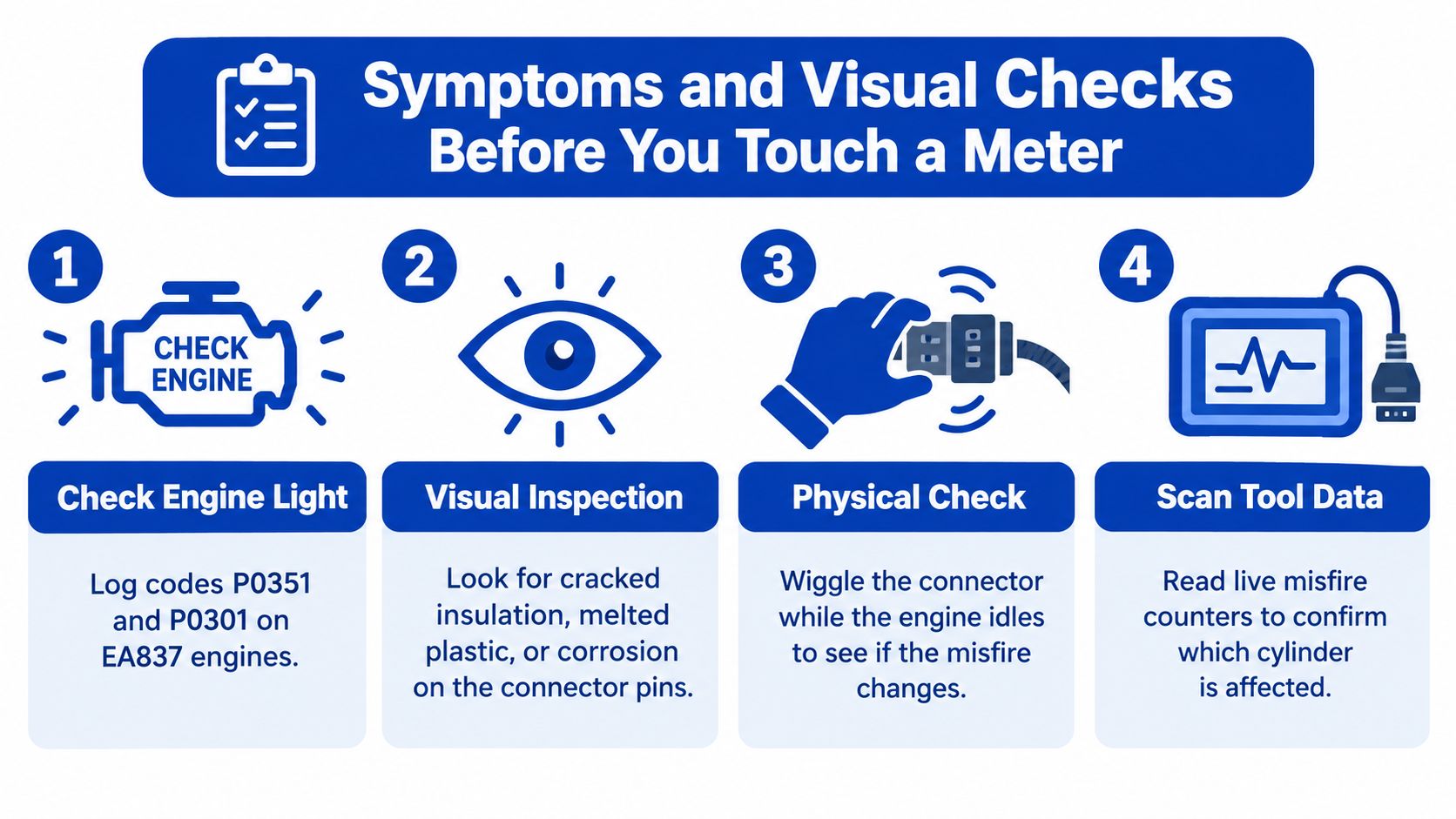
Check what your eyes and hands can tell you
Look for a cracked or melted housing, a broken locking feature, a distorted seal, and corrosion or moisture around the terminals. Check whether any terminal sits farther back in its cavity than its neighbors. A pushed-back pin may still make intermittent contact, which is why a connector can look attached while the circuit cuts out over bumps or during engine movement.
Follow the harness a short distance from the plug. Watch for stretched insulation, a tight bend, oil contamination, or damage where the branch is secured. Gently move the connector and nearby harness while watching live misfire counters. Don't pull on the wires, and keep hands and tools clear of moving or hot parts.
Use a coil swap to localize, not guess
If access and the service procedure allow it, swap the suspect coil with one from a cylinder that isn't misfiring. Clear or record the relevant data, then run the engine under conditions that reproduce the fault. If the misfire moves, the coil becomes the leading suspect. If it stays on the original cylinder, the original connector and its circuit deserve closer testing.
A step-by-step Audi ignition-coil replacement guide can help with safe access and handling. Before using a meter, make sure the connector locks securely, the seal isn't displaced, the terminals aren't corroded or recessed, and the harness isn't visibly strained. Those simple checks often catch damage that a code reader can't identify by itself.
Connector Pinouts and EA837 EA825 Fitment Differences
Don't assume that a connector is correct because it clicks onto the coil. Similar-looking housings can have different cavity assignments, and coil versions may differ across engine and model applications. Pin function must come from the wiring diagram for the exact vehicle, not from the shape of a plug or a generic online diagram.
A coil circuit commonly includes a power supply, an ECU command or control connection, and a ground path. Some designs use an additional terminal for another control or feedback function. The number of terminals alone doesn't tell you which cavity performs which job, nor does a physically matching shell guarantee that the coil and harness agree electrically.
Fitment needs the exact vehicle details
| Engine | Common models | Pins | Fitment note |
|---|---|---|---|
| EA837 3.0T V6 | S4, S5, SQ5, Q7, A6, A7, A8 | Verify by vehicle wiring diagram | Connector and harness routing vary by application. Check model year, engine code, and cavity map before ordering. |
| EA825 4.0T V8 | RS6, RS7, S6, S7 | Verify by vehicle wiring diagram | Tight coil access makes careful connector release and harness routing important. Confirm the correct connector and terminal positions for the specific vehicle. |
This table is a fitment prompt, not a pinout. Without the vehicle-specific wiring diagram, assigning a universal terminal count or pin function to every model risks sending a DIYer to the wrong cavity. A plug that seats but has a mismatched assignment can create a no-start, a persistent misfire, or a damaged component.
Match the circuit, not just the shell
Before ordering a replacement, compare the vehicle identification and engine code with the parts listing, then confirm the connector's cavity layout against Audi service information. Check the secondary lock and wire exit direction as well. A housing that looks right from the front can still differ in terminal arrangement, seal, or retention details.
This matters especially when parts come from another model year or market. Don't move terminals around based on a photo alone. For broader context on Audi V8 platform packaging, see this overview of the Audi supercharged V8 platform, then use the wiring diagram for your own car to identify each cavity.
Testing the Connector with a Multimeter
A voltage reading at rest is a starting point, not a verdict. The useful question is whether the circuit maintains supply and ground when the connector is assembled and the engine is operating under the conditions that trigger the misfire. Back-probe carefully from the rear of the connected plug with a suitable fine probe. Don't pierce insulation or force an oversized probe into a female terminal, because either can create a new problem.
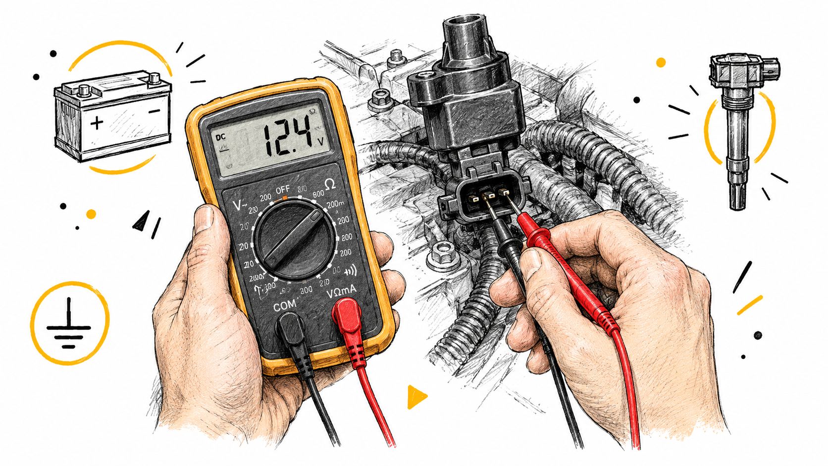
Check supply and ground under operating conditions
Use the correct wiring diagram to identify the power terminal. With the connector disconnected and ignition on, HELLA's general procedure expects more than 10.5 V at the specified supply terminal, but the vehicle's service information takes precedence. If voltage is low, inspect the relevant fuse, relay, harness, and connections instead of assuming the coil is bad. A general ignition-coil test procedure from HELLA outlines this supply check.
Next, measure voltage drop on the ground side while the circuit is under load. A practical benchmark is below roughly 0.1–0.2 V between the coil ground path and battery negative. A higher reading directs attention to resistance in the ground path, terminals, or wiring. Watch the reading during cranking or when the engine condition reproduces the fault, if the service procedure permits.
A continuity beep only tells you that a path exists at the meter's test current. It doesn't prove the terminal can hold contact under load.
Check resistance only with power removed
If you're checking coil resistance, switch power off and follow the Audi specification for that exact coil. Generic resistance figures don't substitute for vehicle data, and some coil designs don't lend themselves to a simple resistance verdict. Resistance testing can also miss a spread female terminal, because the meter probes may contact the terminal in a way the coil pin doesn't.
If the connector reading differs from a check at the ECU end, inspect the wire and terminals between those points. Never ohm-test an energized circuit, and don't probe an unidentified cavity. This Audi camshaft-sensor diagnostic overview is a useful reminder that electrical diagnosis depends on identifying the correct circuit, not touching a meter to a connector.
For a clear view of proper test technique, use this demonstration as a visual reference. Confirm its steps against the wiring diagram and service procedure for your Audi before testing.
Coil Swap or Connector Repair Decision Tree
A coil swap answers one specific question: does the misfire move with the coil? It doesn't test terminal tension, the harness under load, or the ECU's control signal. Use the result together with the visual and voltage checks rather than treating any single test as a complete diagnosis.
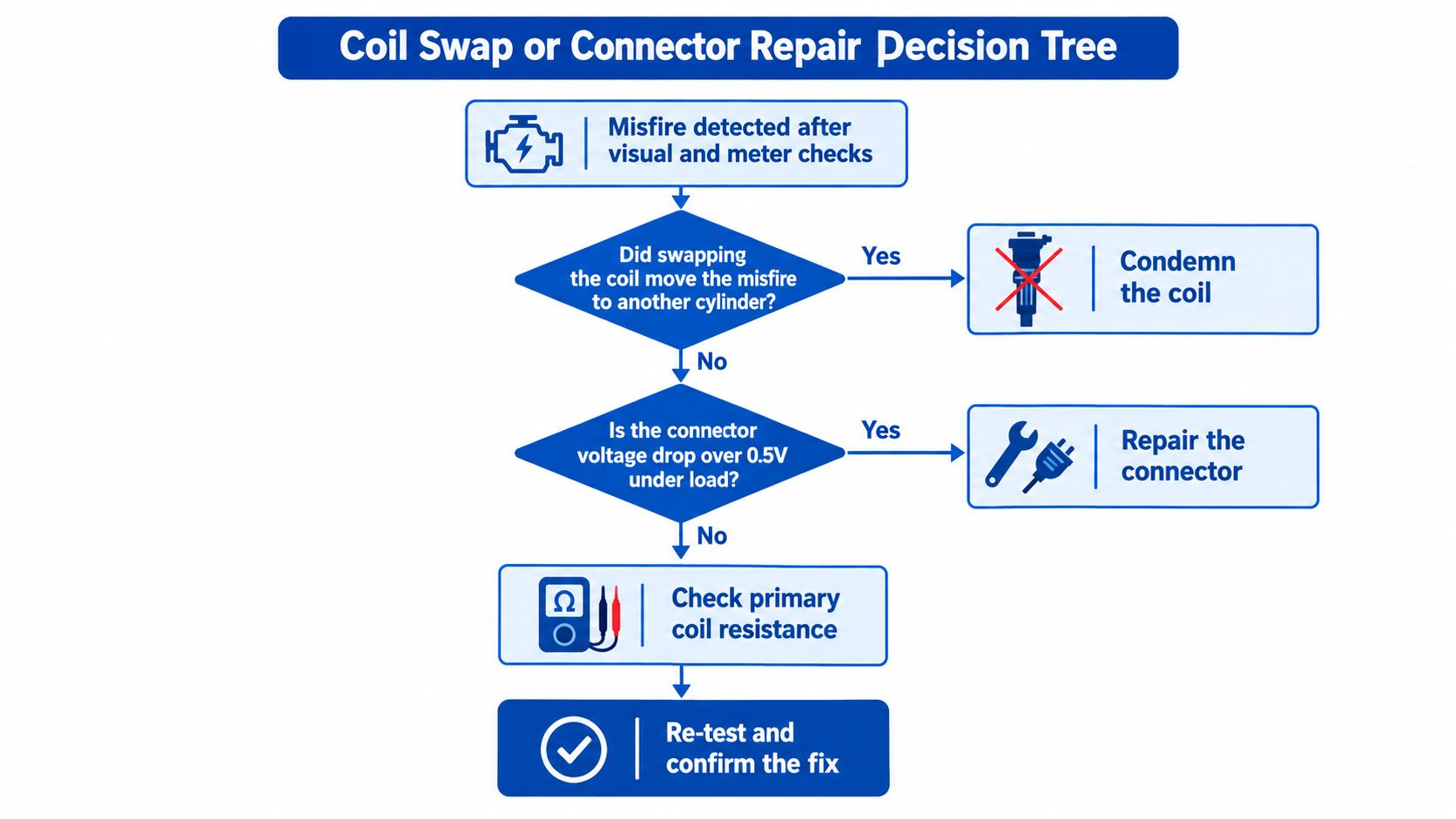
Follow the fault before replacing parts
- The misfire follows the coil: The coil is the stronger suspect. Confirm the result under the conditions that trigger the fault, then inspect the receiving cylinder's connector before reinstalling parts.
- The misfire stays on the original cylinder and supply is stable: Test the connector terminals, harness, spark plug, and control circuit. Don't condemn the coil just because it was on the affected cylinder.
- The misfire stays, but voltage or signal is intermittent: Focus on terminal grip, a partial wire break near the plug, harness movement, or the ECU driver. A clean reading while stationary won't rule out an intermittent fault.
- The connector and coil checks don't isolate it: Follow the vehicle-specific diagnostic procedure and examine other cylinder-specific causes rather than replacing parts by guesswork.
A coil can pass a bench resistance check and still misfire on the car. The connector may lose contact under engine movement, or the supply may sag only when the circuit is loaded. That's why live data, a careful back-probe, and a controlled coil swap work better together than resistance readings alone.
Choose a repair that preserves the circuit
Repair an individual terminal only when the housing is sound and you can install the correct replacement terminal with the correct wire gauge, plating, crimp, seal, and cavity position. Replace the pigtail when the wire is damaged near the connector, terminal tension is poor, or corrosion has travelled into the conductor. Replace the housing when its locking feature or secondary-retention system no longer holds terminals securely.
The terminal position assurance feature, often called TPA, must return to its locked position after the terminals are seated. Don't force it closed over a terminal that hasn't clicked into its cavity. After the repair, repeat the electrical checks and confirm that the misfire counter stays quiet during the same conditions that previously brought the fault back.
Replacing the Connector and Securing the Repair
A durable connector repair depends on matching the parts and preserving the housing's retention system. Before starting, identify the correct pigtail or terminal for the vehicle. Have the right terminal-extraction tool, matching seals, an appropriate crimp tool, and temperature-suitable dielectric grease ready. If the connector is damaged, the replacement shell must match the original cavity layout and locking features.
Remove and rebuild without losing the cavity map
- Isolate power and gain access. Follow the vehicle's battery-isolation procedure. Release the harness carefully, and don't use the wires to pull the plug off the coil. EA837 access can require more disassembly around the intake manifold; on the EA825, account for the harness routing and clearance around the V8 coils.
- Record the terminal positions. Photograph the connector face and note each wire's cavity before removing anything. Release the secondary lock as designed, then use the correct extraction tool to remove a terminal. Pulling with pliers can distort the terminal or break its retention tang.
- Install the matched terminal or pigtail. Use a replacement with the correct wire size, terminal finish, cavity position, and seal dimensions. Make a proper conductor and seal crimp. If the wire is heat-damaged, corroded, or broken farther up the branch, replace the pigtail rather than joining onto compromised copper.
- Reassemble the lock. Seat each terminal until its retaining feature engages, then reinstall the TPA. Check that no terminal has backed out and that the connector locks to the coil without force.
Avoid packing the connector with grease. Use only a compatible, temperature-rated product as appropriate to the connector design, and keep the terminal contact surfaces clean.
Verify it hot and moving
After reconnecting the battery, check that the lock is secure and the harness isn't stretched or touching a hot component. Start the engine and monitor the live misfire counters while gently moving the harness. Then reproduce the original fault during a road test and recheck after the engine has heat-soaked. A brief smooth idle doesn't prove that an intermittent connection is fixed.
If the misfire returns, revisit the voltage and signal checks before replacing another part. The repair is complete only when the connector remains secure and the cylinder stays clean under the operating conditions that exposed the fault.
Misfires That Linger and Platform-Specific Traps
A connector can be repaired correctly and still not cure the misfire. Oil or moisture may keep contaminating the area, a wire may be broken farther back in the harness, or the ECU's control circuit may be at fault. Don't repeat a connector repair without checking why the original connection degraded.
Look beyond the plug
On EA825 applications, inspect for oil contamination around the cam-cover area and coil connectors. On the EA837, check for oil vapor and residue near the coil harness, especially if there are signs of a PCV or related sealing problem. Contamination can compromise the connection over time, but it doesn't prove the connector is the only failed component.
An ECU power-output-stage problem can also resemble an intermittent connector fault. A circuit may show a plausible reading at rest and fail when commanded or loaded. If supply, ground, terminal grip, and harness continuity check out but the coil command remains abnormal, use the Audi diagnostic procedure to evaluate the control side rather than installing more coils.
Keep these application-specific checks in mind:
- RS7: Inspect harness routing in tight areas and confirm it hasn't been pinched or stressed during prior work.
- SQ5: Consider heat exposure around the supercharger when evaluating an intermittent fault.
- S4 and A6 3.0T: Check the wiring path and engine-to-body transition for chafe or strain.
When the misfire persists
If the connector is clean and electrically sound, widen the diagnosis to the plug, injector, mechanical condition, and ECU control. A persistent misfire isn't proof of a bad injector either. If injector concerns become plausible, this overview of ultrasonic injector cleaning gives useful context, but testing should still determine whether the injector is responsible.
How long does the repair take? It depends on access and whether the connector can be reached without removing other components. A straightforward pigtail repair is different from a job that requires substantial intake-side access.
Do aftermarket coils mean the connector is bad? No. A coil's brand doesn't establish connector health. Check fit, terminal seating, and the circuit under the conditions that trigger the misfire.
When is a shop the better call? If access requires disassembly you're not equipped to handle, terminals are damaged inside the harness, or the ECU control signal needs advanced testing, choose a technician with Audi wiring information and suitable diagnostic tools.
Vorsprung Autowerk offers Audi-focused performance and maintenance parts, including components for EA837 and EA825 applications, alongside ECU-related services. If you're sourcing parts or planning the next step in your diagnosis, visit Vorsprung Autowerk and confirm fitment for your vehicle before ordering.


